Description
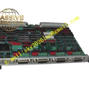
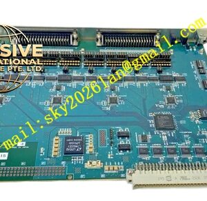
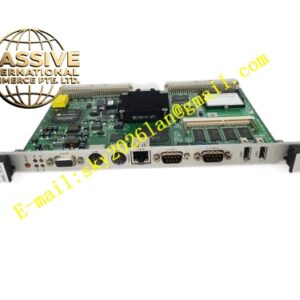
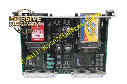
Densan DVE‑540A(9391)
Technical Specifications: Bus standard: VME ANSI/IEEE 1014 Form factor: 6U single‑slot VME plug‑in module Supported input signal: analog voltage, analog current ADC resolution: 16‑bit Isolation withstand voltage: 1500 VAC between field side and VME bus side Operating temperature: 0 ℃‑55 ℃ Storage temperature: -40 ℃‑85 ℃ Relative humidity: 5%‑95% non‑condensing Protection grade: IP20 Backplane connector: DIN 41612 J1
Functional Features: Multi‑channel galvanically isolated analog input channels with enhanced anti‑interference design. 16‑bit high‑precision analog‑digital conversion. Per‑channel programmable input‑range configuration via VME register. Upgraded multi‑stage low‑pass filtering circuit for strong noise suppression. Advanced hardware self‑calibration for temperature‑drift error compensation. Front‑panel LED indicators for power and fault alarm. VME interrupt generation upon completion of sampling conversion. Comprehensive power‑on self‑diagnosis function.
Application Scenarios: Semiconductor equipment located in high‑electromagnetic‑interference workshop, heavy‑duty industrial automation VME control cabinet, automated test system under complex field noise environment, new‑energy equipment high‑precision parameter monitoring, factory special‑purpose machinery process‑measurement cabinet.
Performance Parameters: Full‑scale measurement accuracy: ±0.04% Configurable sampling rate for each independent channel Vibration resistance: 10 Hz‑150 Hz, 0.5 g Shock resistance: 10 g peak acceleration, 11 ms duration MTBF value: 191000 hours
Material Composition: Front‑panel uses anti‑oxidation treated aluminum alloy. Main printed‑circuit‑board adopts FR‑4 high‑Tg glass‑fiber epoxy substrate. Backplane connector contacts use gold‑plated copper alloy. Signal conditioning, filtering and ADC components adopt enhanced industrial‑grade specification. Fastening hardware uses nickel‑plated steel.
Structural Features: 6U single‑slot VME plug‑in mechanical construction. Metal front panel fitted with locking ejector handles and LED status lamps. Rear high‑density gold‑plated DIN connector connects VME rack backplane. PCB layout establishes independent enhanced‑filter zone, analog‑signal zone and digital‑logic zone separated by isolation barrier. Analog signal traces implement strict impedance‑matching routing rules. Ventilation cutouts support passive heat dissipation.
Working Principle: Field analog signal enters enhanced multi‑stage filtering circuit before galvanic isolation unit. After noise elimination and isolation processing, signal delivers to high‑precision ADC chip. ADC converts analog physical quantity into digital measurement value. VME host controller reads sampling result by accessing hardware registers on VME backplane bus. Upgraded on‑board calibration circuit compensates measurement error generated by ambient‑temperature variation. Fault and channel status information can be read through VME bus registers.
Installation Requirements: Insert module to designated slot of 6U VME rack chassis, engage locking ejector handles and tighten front‑panel mounting screws. Ensure sufficient ventilation heat‑dissipation space inside cabinet. Apply high‑quality shielded twisted‑pair cable for analog‑signal field wiring. Separate analog‑signal cables away from high‑power drive cables. Disconnect rack total power supply before plugging or removing this circuit board. Complete static discharge operation before touching bare printed‑circuit‑board surface.
Precautions for Use: Never apply input signal beyond configured measuring range. Wear anti‑static wristband for all maintenance and inspection work. Keep ventilation openings free of dust accumulation. Forbid installation inside environment containing corrosive gas. Conduct periodic hardware calibration according to maintenance specification. Regularly inspect shielding grounding performance of field analog signal cables.