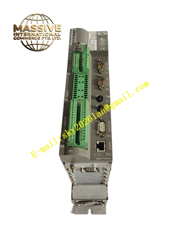
Description
ELAU PS‑5POWERSUPPLYISH
Technical Specifications Main Mains Input: Single‑phase / 3‑phase AC 220‑240 V, 48‑62 Hz Control Power Input: DC24 V,‑15 % / +25 %, max 13 A DC‑Bus Intermediate‑Circuit Voltage Range: 270 V DC to 680 V DC Integrated Bleeder Activation Threshold: 830 V DC Bleeder Cut‑off Threshold: 810 V DC Bleeder Continuous Power Rating: 200 W Bleeder Peak Power Rating: 28 kW Max Permitted DC‑Bus Output Continuous Current: 20 A for 3‑phase mains input; 10 A for single‑phase mains input Communication Interface: SERCOS fiber‑optic interface Protection Class: IP20 Operating Ambient Temperature:‑10 °C to +50 °C Storage Temperature:‑25 °C to +70 °C Mounting Type: Standard DIN‑rail cabinet mounting Cooling Mode: Natural convection cooling
Functional Features Provides stabilized high‑voltage DC‑bus intermediate‑circuit power supply for ISH series integrated‑servo‑motor group. Built‑in active‑bleeder circuit consumes regenerative‑energy generated during motor‑deceleration‑phases, suppresses DC‑bus over‑voltage risk. Integrated SERCOS fiber‑optic‑bus interface uploads power‑supply‑operating‑status, fault‑codes and real‑time electrical‑parameter‑data to upper‑level PacDrive motion‑controller. Complete hardware‑diagnosis function monitors mains‑input‑status, intermediate‑circuit‑voltage, internal‑module‑temperature and bleeder‑circuit‑health‑state. Non‑volatile‑memory stores fault‑event‑history‑records. Relay‑type ready‑status output signal delivers hardware‑operational‑state notification to external‑control‑system. Modular DIN‑rail mounting‑structure supports flexible cabinet‑layout‑configuration for decentralized‑drive‑system architecture.
Application Scenarios Decentralized‑drive multi‑axis packaging‑machinery; modular‑structure film‑converting‑production‑lines; automated‑processing‑equipment adopting ISH integrated‑servo‑motor hardware‑solution.
Performance Parameters Supports power‑supply for up to 25 units of ISH integrated‑servo‑motors under reasonable‑load‑distribution‑condition. Bleeder‑circuit responds instantaneously to regenerative‑energy‑surge during fast‑motor‑deceleration‑processes. SERCOS‑bus transmits power‑supply‑diagnosis‑data with microsecond‑level update‑cycle. Fault‑history‑data remains preserved after equipment‑power‑off‑cycle.
Material Composition Aluminum‑alloy‑shielding housing, FR‑4 high‑voltage‑rated multilayer‑printed‑circuit‑board, high‑power‑rectifier‑bridge‑assembly, power‑semiconductor‑bleeder‑switch‑components, high‑voltage‑electrolytic‑capacitor‑bank, fiber‑optic‑transceiver‑module, non‑volatile‑flash‑memory‑chips, plug‑in screw‑lock‑terminal‑blocks, SMD LED‑status‑indicator‑components.
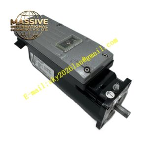
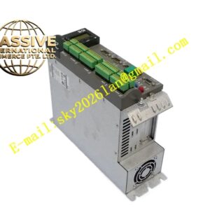
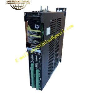
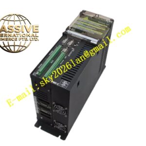
Structural Characteristics Standard DIN‑rail‑compatible vertical‑housing‑form‑factor. Front‑panel is equipped with LED‑status‑indicator‑array, SERCOS fiber‑optic‑connector‑ports. Upper‑housing‑section accommodates mains‑input‑power‑terminals and DC‑bus‑output‑power‑terminals for ISH‑motor‑group‑connection. Lower‑housing‑section arranges DC24 V control‑power‑input‑terminals and ready‑status‑relay‑output‑terminals. Metal‑identification‑nameplate permanently prints complete part‑number PS‑5POWERSUPPLYISH. Internal‑high‑voltage‑circuit‑area implements physical‑isolation‑structure for safety‑protection‑purpose.
Working Principle AC‑mains‑voltage flows into internal‑rectifier‑bridge‑assembly and converts into DC‑bus intermediate‑circuit‑voltage for ISH‑integrated‑servo‑motors. When connected‑motors execute‑deceleration‑motion, regenerative‑energy flows back into intermediate‑circuit‑capacitor‑bank and raises DC‑bus‑voltage. Once voltage‑value exceeds bleeder‑activation‑threshold, power‑semiconductor‑switch turns on and redundant‑regenerative‑energy dissipates through bleeder‑resistor‑assembly. On‑board‑monitoring‑circuit continuously samples mains‑input‑condition, DC‑bus‑voltage magnitude and internal‑module‑temperature. SERCOS fiber‑optic‑interface transmits real‑time‑status‑data and fault‑information to upper‑level‑motion‑controller. Ready‑status‑relay‑output generates hardware‑OK‑signal when all internal‑diagnosis‑items pass inspection.
Installation Requirements Install module onto standard DIN‑rail inside fully‑grounded industrial‑control‑cabinet. Reserve adequate surrounding‑clearance for natural‑convection‑heat‑dissipation. Strictly follow‑torque‑specifications for high‑voltage‑power‑terminal‑tightening‑operation. Use dedicated heavy‑gauge shielded DC‑bus‑power‑cables to connect PS‑5‑power‑supply‑unit with ISH‑integrated‑servo‑motors. Physically separate high‑voltage‑DC‑bus‑wiring‑routes from low‑signal‑communication‑cable‑paths. Connect protective‑earth‑terminal reliably to cabinet‑main‑ground‑busbar. Comply with SERCOS fiber‑optic‑cable minimum‑bending‑radius‑rules during‑wiring‑work.
Usage Notes Hot‑plugging high‑voltage DC‑bus‑power‑connectors under‑powered‑condition is strictly forbidden. Confirm total‑power‑consumption‑calculation of connected‑ISH‑motor‑group before commissioning, avoid overloading power‑supply‑unit. Wear anti‑static‑wrist‑strap when performing‑maintenance‑operations on internal‑circuit‑components. Prevent hardware‑unit exposure to conductive‑dust, oil‑mist and corrosive‑industrial‑vapors. Operate hardware strictly within published ambient‑temperature‑operating‑limits.