Description
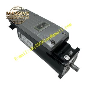
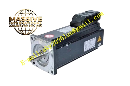
ELAU SM‑100‑40‑050‑P0‑45‑M1‑B1Technical Specifications: Rated power 2.0 kW, rated speed 4000 rpm, maximum speed 4500 rpm, continuous stall torque 4.8 Nm, peak torque 15.5 Nm, rotor inertia 1.2 kg·cm², insulation class F, IP65 protection grade, frame size 100 mm B5 flange, 19 mm flat‑key shaft, built‑in holding brake B1, power connector P0 type, resolver M1 feedback, natural convection cooling, weight 7.8 kg, ambient working temperature 0 °C‑40 °C.
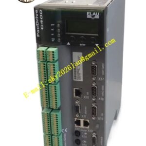
Functional Features: Integrated spring‑applied electromagnetic holding brake maintains shaft position when power cuts off. Resolver feedback provides high anti‑interference position signal for harsh industrial environment. Low‑inertia rotor realizes fast acceleration response. Built‑in PTC temperature sensor monitors winding temperature. High sine‑wave back‑EMF characteristic lowers system current consumption. Support direct parameter configuration via PacDrive control software.
Application Scenarios: Vertical lifting axes of automation equipment, gantry robots, hopper positioning units, machine‑tool auxiliary axes, automated storage retrieval systems, lifting‑type packaging machines.
Performance Parameters: Brake holding torque 8 Nm, brake operating voltage 24 V DC, resolver signal‑to‑noise ratio meets industrial heavy‑duty standard, CE and UL compliance, three‑phase 400 V AC input.
Material Composition: Die‑cast aluminum motor housing, silicon‑steel laminated stator core, neodymium‑iron‑boron permanent‑magnet rotor, copper winding coils, quenched alloy steel output shaft, brake friction disc made of high‑wear‑resistant composite material, reinforced plastic connector housings.
Structural Features: Standard B5 front‑flange mounting layout, power and resolver signal separate top‑mount connectors, holding brake assembly installed at non‑drive end of rotor shaft, shaft‑end sealing ring for dust‑water resistance, integrated PTC thermal sensing components inside stator winding.
Working Principle: Stator three‑phase sinusoidal excitation generates rotating magnetic field to drive permanent‑magnet rotor for torque output. Resolver detects rotor angular position and feeds back to servo drive for closed‑loop control. The built‑in holding brake locks rotor shaft by spring force when 24 V brake power supply de‑energizes; brake releases immediately upon applying rated DC voltage.
Installation Requirements: Mount on rigid low‑vibration base surface. Complete brake power‑supply wiring strictly following pin definition. Guarantee coupling concentricity error less than 0.05 mm. Maintain adequate surrounding space for heat dissipation. Separate power wiring and resolver feedback wiring. Implement reliable protective earthing for motor housing.
Usage Notes: Do not use holding brake for dynamic braking during motor running; brake only serves static‑position retention. Configure controller feedback parameter to resolver mode. Avoid condensation inside motor housing. Inspect brake function periodically. Prevent mechanical impact on output shaft during installation.