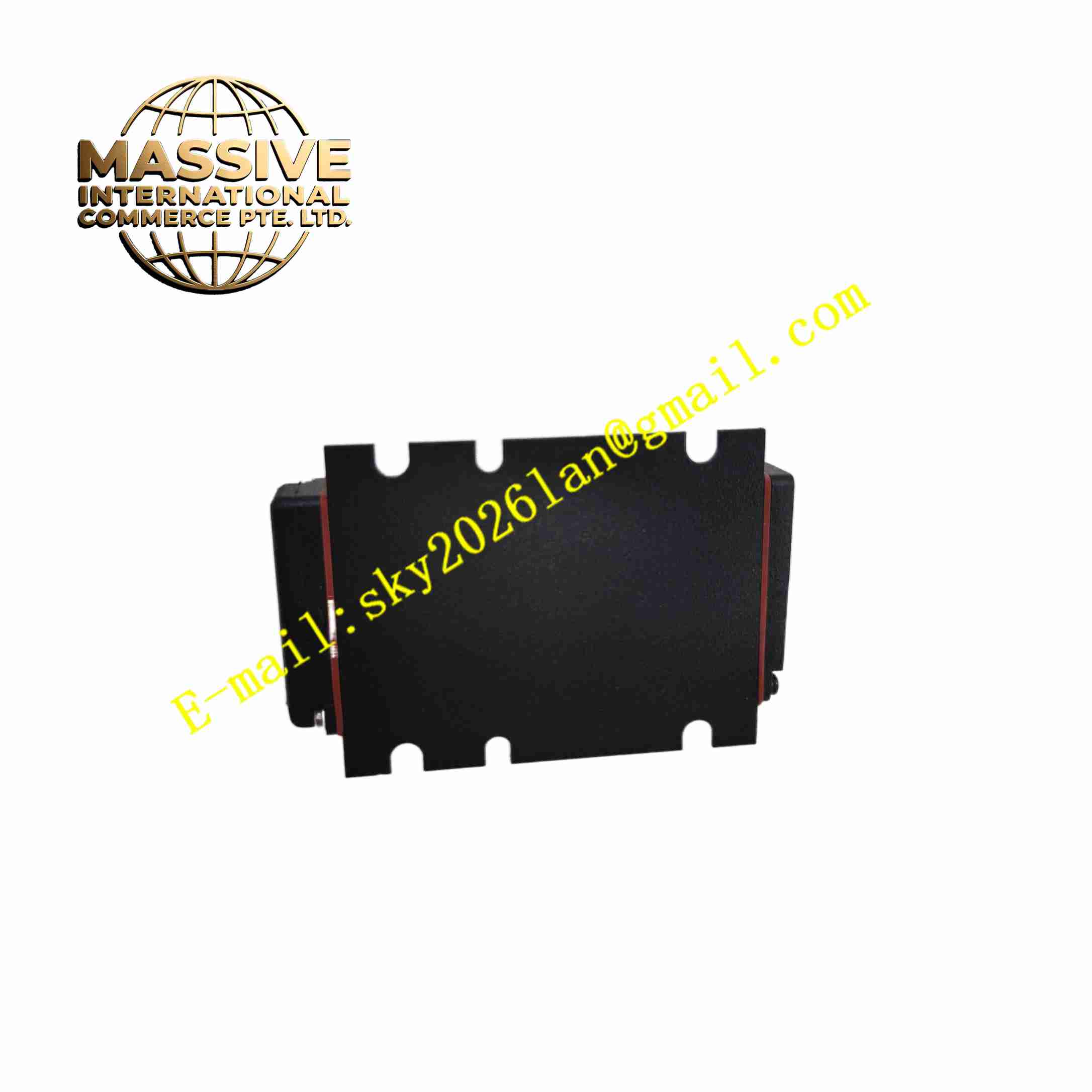
Description
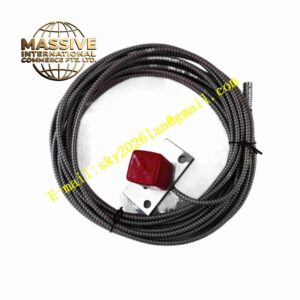
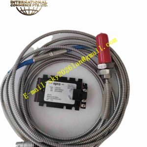
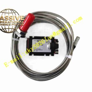
EPRO PR6425010-130+CON021/915-040
Technical Specifications Model: PR6425010-130 probe + CON021/915-040 signal converter Measurement Principle: Eddy current non-contact displacement measurement Probe Integrated Cable Length: 13 meters Measuring Range: 0 ~ 4 mm Output Signal: 4-20mA or 0~10V analog signal Power Supply for CON021: -24VDC Probe Operating Temperature: -35℃ ~ +180℃ Converter Operating Temperature: -20℃ ~ +65℃ Storage Temperature: -40℃ ~ +85℃ Relative Humidity: 5% ~ 95% non-condensing Probe Protection Grade: IP67 Mounting Method: Threaded mounting for probe, DIN rail mounting for converter
Functional Features Non-contact measurement eliminates mechanical wear between probe and rotating metal shaft. 4mm wide measuring range meets measurement requirement of large rotor axial floating displacement. 13-meter integrated shielded coaxial cable supports long-distance field wiring. High temperature resistant stainless steel and ceramic packaging adapts to high temperature bearing housing environment. CON021/915-040 converter assembly processes high-frequency probe signal and outputs standard analog signal. Built-in cable break detection function outputs fault alarm when probe cable suffers damage. High measurement resolution captures micrometer-level tiny displacement variation in full measuring range. Shielded coaxial cable suppresses electromagnetic interference from industrial power equipment.
Application Scenarios Steam turbine thrust axial displacement monitoring, heavy-duty centrifugal compressor shaft position protection, large hydroelectric generator shaft vibration monitoring, gas turbine rotor displacement measurement, large industrial fan and pump rotor condition monitoring.
Performance Parameters High linearity maintained within full 4mm measuring range. Micrometer-level displacement resolution for capturing micro vibration amplitude. Cable break detection reliably identifies cable damage and triggers fault signal. Output analog signal maintains stable linear relation with gap variation after long-time continuous operation. Probe keeps stable sensing characteristic under continuous high temperature and vibration environment. CON021/915-040 converter assembly has stable signal conversion performance for 13-meter long cable channel.
Material Composition Probe housing: High temperature resistant stainless steel alloy. Sensing coil: High temperature enameled copper winding encapsulated in ceramic insulator. Probe cable: Fluorine plastic insulated shielded coaxial cable. CON021/915-040 housing: Anodized aluminum alloy metal casing. PCB inside converter: FR4 multi-layer printed circuit board with conformal coating. Core Electronic Components: High-frequency oscillation chip, signal conditioning circuit, A/D converter, analog output driving chip, cable fault detection circuit. Fasteners: Stainless steel probe lock nut, DIN rail clip for converter. Insulating material: High temperature ceramic and fluorine plastic insulator.
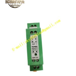
Structural Features Cylindrical threaded probe body, ceramic tip encapsulates wide-range sensing coil. 13-meter shielded coaxial cable integrated at rear of probe body. External thread matched with lock nut to fix probe after gap adjustment. /915-040 converter is rectangular aluminum casing with DIN rail clip on back side. Terminal block arranged on converter side for power supply and analog signal wiring. Internal circuit layout separates high-frequency excitation circuit and analog signal processing circuit.
Working Principle /915-040 signal converter generates high-frequency alternating excitation current and transmits it to probe coil through 13-meter coaxial cable. Alternating magnetic field radiates outward from probe tip. Eddy current is induced on metal shaft surface near probe tip. Eddy current produces reverse magnetic field and changes impedance of probe coil. The coil impedance value changes linearly with gap between probe tip and metal shaft. The converter detects coil impedance variation, calculates gap value and converts measurement result into standard analog signal. If probe cable breaks, fault detection circuit detects abnormal coil impedance and outputs fault state. Upper monitoring system receives analog signal and calculates shaft vibration and shaft position value.
Installation Requirements Screw PR6425010-130 probe into threaded hole of bearing housing, adjust probe tip and shaft gap into working range, tighten lock nut. Lay 13-meter coaxial cable inside protection conduit, avoid sharp bending and tensile pulling. Mount /915-040 converter on DIN rail inside control cabinet, keep away from high power heat source and high voltage cable. Connect -24VDC power supply and analog signal output wiring to converter terminal block. Use shielded twisted pair cable for analog signal transmission, single-point grounding of shielding layer. Set target material parameter in monitoring system according to shaft metal material. Complete gap calibration with standard target block before machine startup.
Usage Precautions Probe tip must not touch rotating shaft during machine running, collision will permanently damage probe coil and ceramic tip. Do not pull, squeeze or bend coaxial cable below minimum bending radius. Cutting and splicing integrated coaxial cable is forbidden, which destroys measurement linearity. /915-040 converter must be installed inside cabinet within rated temperature range. Check probe installation gap and cable integrity during regular equipment maintenance. Strong magnetic field near probe installation point affects measurement precision. Calibration is mandatory after probe replacement.