Description
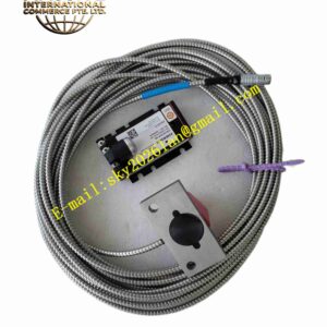
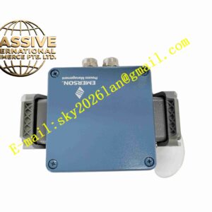
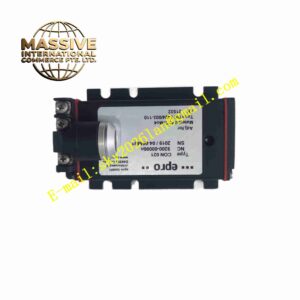
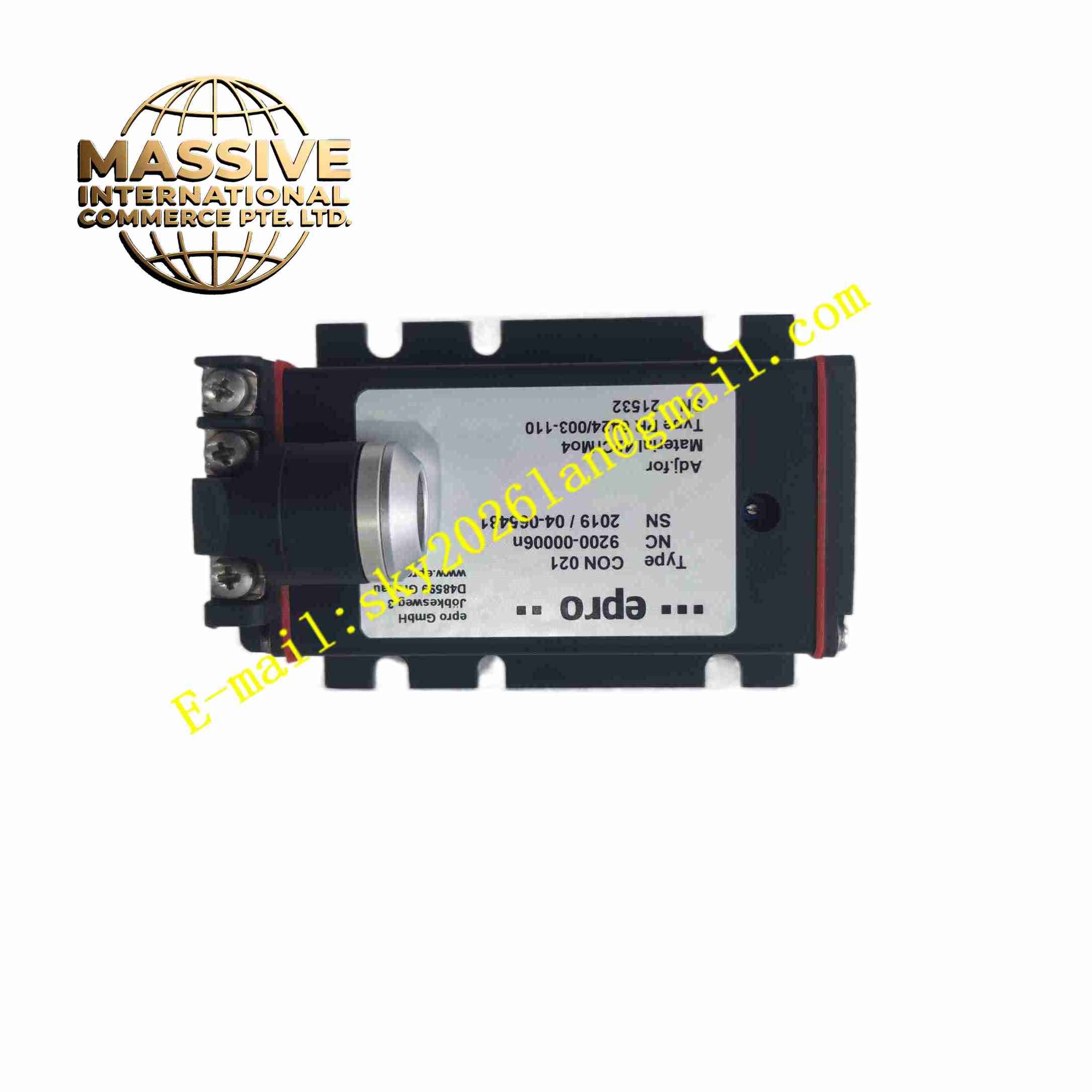
EPRO PR6424/003-110 + CON021
Technical Specifications
- Brand: EPRO, part of Emerson
- Sensor Model: PR6424/003-110
- Transducer Model: CON021
- Sensor Type: Non-contact eddy current proximity sensor
- Probe Series: PR6424, typically 8 mm class probe
- Typical Linear Range: ±2.0 mm for PR6424 with standard CON021 configuration
- Extended Range: Up to ±4.0 mm, ±6.0 mm, ±8.0 mm, or ±10.0 mm with CON021/91 variants
- Frequency Response: 0 Hz to approximately 10 kHz to 20 kHz
- Rise Time: Less than 15 µs
- Supply Voltage: Typically -24 V DC for CON021
- Output Signal: DC voltage with superimposed AC vibration signal
- Linear Output Range: Typically -4 V to -20 V with -24 V supply
- Output Impedance: Approximately 100 kΩ
- CON021 Protection Rating: IP20
- Probe Protection Rating: Depends on probe variant and cable termination
- Calibration Material: Typically 42CrMo4 / AISI 4140 steel unless otherwise specified
Functional Features
- Provides non-contact measurement of shaft radial and axial displacement.
- Suitable for both static position and dynamic vibration measurement.
- Factory-calibrated probe, cable, and transducer combination.
- High linearity over a wider range than PR6423 in standard configuration.
- Supports integration into turbine monitoring and protection systems.
- Resistant to oil, moisture, and many industrial contaminants.
- Compatible with EPRO MMS 3000 and MMS 6000 systems.
Application Scenarios
- Steam turbine shaft vibration monitoring
- Gas turbine axial displacement measurement
- Compressor rotor position monitoring
- Large fan and pump shaft vibration monitoring
- Generator shaft eccentricity detection
- Industrial turbomachinery protection systems
- Bearing clearance and thermal growth monitoring
Performance Parameters
- Linear range for PR6424 with standard is typically ±2.0 mm.
- Linearity error for PR6424 with CON0X1 is typically ≤1.5 percent of full scale.
- Linearity error for with CON0X1/91 extended-range versions is typically ≤1.0 to 2.0 percent, depending on range.
- Zero-point temperature drift is approximately 200 mV per 100 K.
- Sensitivity temperature drift is typically less than 2 percent per 100 K.
- Time drift is typically no more than 0.3 percent.
- Supply voltage influence is typically less than 0.2 percent per volt.
Material Composition
- Probe housing typically made of stainless steel
- Probe tip assembly typically uses PEEK or similar insulating material
- Cable insulation typically uses PTFE
- Connector typically uses LEMO-type metal connector
- transducer housing uses industrial enclosure with screw terminals and LEMO input
Structural Features
- Cylindrical probe body for threaded installation
- Larger measurement range than PR6423 in standard configuration
- LEMO connector or screw terminal cable end depending on variant
- transducer supports panel or DIN-rail mounting
- Screw terminals for power and output signals
- LEMO connector for probe connection
Working Principle
The probe coil is excited by a high-frequency signal from the transducer. As the distance between the probe tip and the conductive shaft surface changes, eddy currents induced in the shaft alter the coil impedance. The transducer converts this impedance change into a proportional DC voltage. The DC level indicates the average shaft position, while the AC component represents dynamic vibration. The system provides a linear output within the calibrated measurement range.
Installation Requirements
- Mount the probe in a rigid bracket or threaded housing.
- Set the static gap within the calibrated linear range.
- Adjust the gap until the output voltage reaches the specified mid-range value, typically around -10 V to -12 V.
- Confirm the exact gap voltage from the calibration certificate.
- Use the correct cable length as specified in the system configuration.
- Keep signal cables away from high-voltage and high-current cables.
- Ground the shield at the transducer end only.
- Install the transducer inside a clean control cabinet.
- Verify power supply polarity and voltage before operation.
Precautions for Use
- Do not interchange probes with PR6423 or PR6426 systems without confirming calibration compatibility.
- Do not use standard in hazardous areas without approved safety barriers.
- Ensure the target surface is conductive ferromagnetic steel unless a special calibration is provided.
- Avoid mounting near slots, holes, or uneven surfaces.
- Recheck gap voltage after mechanical locking.
- Inspect LEMO connectors for contamination or looseness.
- Perform periodic system verification to maintain accuracy.
- Refer to the official EPRO documentation for the exact /003-110 configuration.