Description
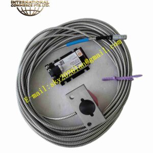
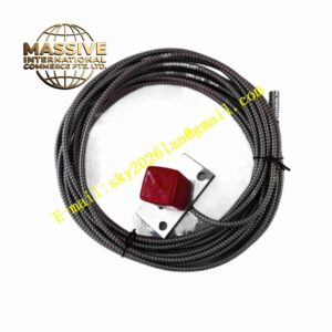
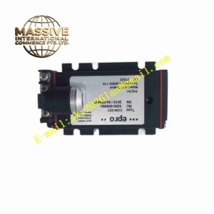
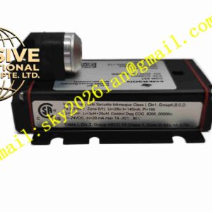
EPRO PR9376010-011
Technical Specifications Model: PR9376010-011 Measurement Principle: Hall effect magnetic flux detection Power Supply: 24VDC, 18~30VDC wide input range Output Signal: Frequency pulse signal proportional to rotational speed Probe Operating Temperature: -40℃ ~ +120℃ Electronics Operating Temperature: -25℃ ~ +85℃ Storage Temperature: -50℃ ~ +150℃ Relative Humidity: 0% ~ 95% non-condensing Probe Protection Grade: IP67 Vibration Resistance: 10g within 10Hz ~ 2kHz Shock Resistance: 100g 1ms half-sine pulse Cable Length: 5 meters standard integrated shielded cable
Functional Features Non-contact magnetic detection, no mechanical contact and wear between probe and gear target. Supports high speed and zero-speed detection, suitable for overspeed protection and zero-speed interlock logic. High resolution pulse output for accurate rotational speed calculation. Wide operating temperature range adapts to harsh industrial field environment. Shielded integrated cable restrains electromagnetic interference. Built-in overvoltage and reverse polarity protection circuit. Compact threaded probe design for installation on gearbox and bearing housing. Suitable for ferrous gear tooth target and magnetic trigger wheel measurement.
Application Scenarios Steam turbine overspeed protection speed monitoring, gas turbine rotational speed measurement, large generator zero-speed interlock, centrifugal compressor speed monitoring, large fan and pump rotational speed detection.
Performance Parameters Measurement accuracy ±1% full scale at 25℃. Temperature drift controlled within specified threshold. Pulse signal has steep edge for reliable counting by monitoring modules. Sensor maintains stable pulse output under continuous mechanical vibration. Circuit protection function prevents damage from reverse power connection and transient surge voltage. Cable shielding restrains conducted interference from high-power frequency converter and motor cables.
Material Composition Probe housing: High strength stainless steel alloy. Sensing chip: Hall effect semiconductor sensing element. Internal circuit board: FR4 printed circuit board with conformal coating. Signal cable: Shielded multi-core flexible cable. Threaded fitting and lock nut: Stainless steel material. Sealing material: High temperature resistant fluorine rubber sealant.
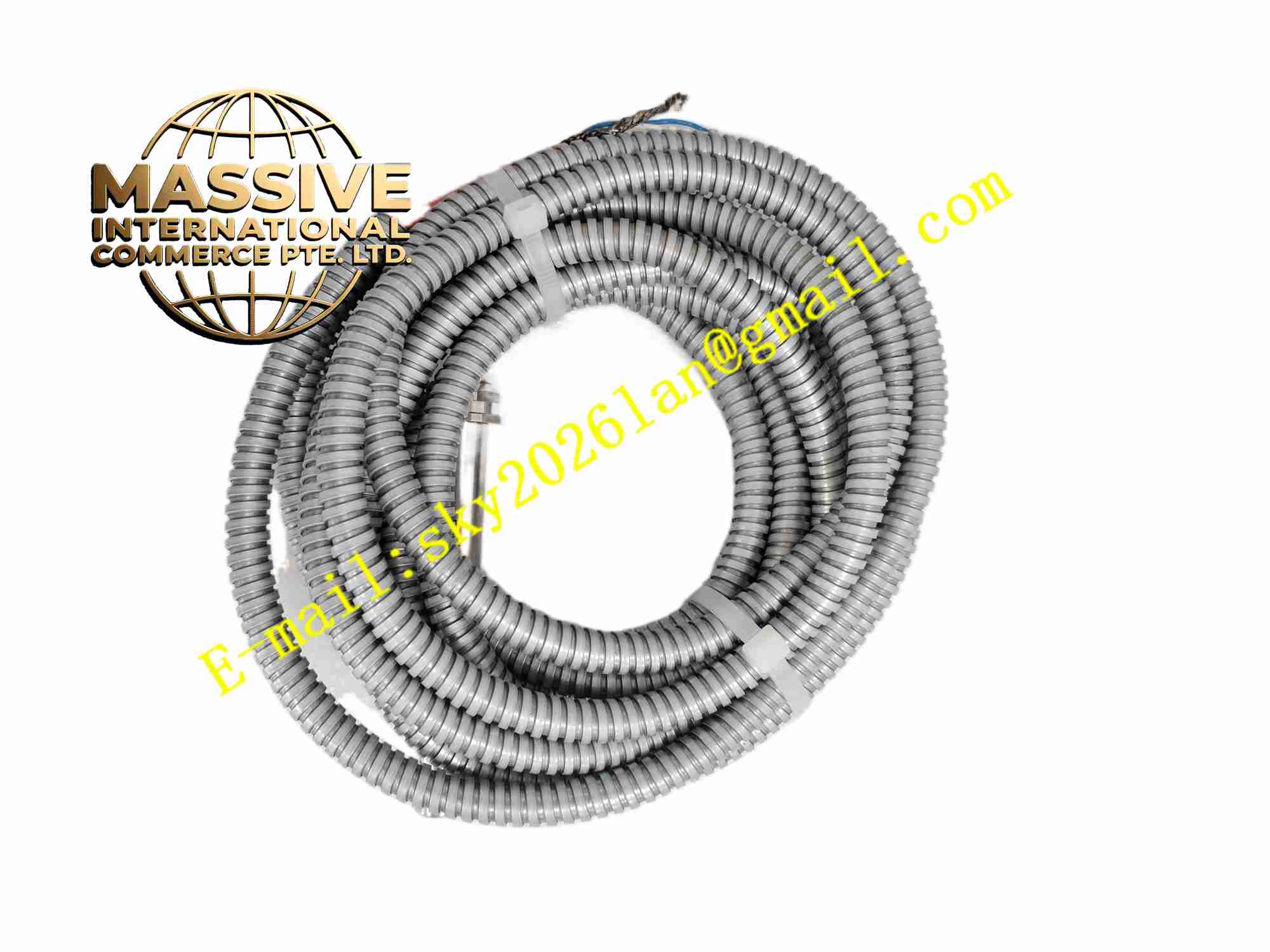
Structural Features Cylindrical threaded probe body, Hall sensing chip encapsulated inside probe tip. 5-meter integrated shielded multi-core cable extends from probe rear end. External thread with lock nut for gap adjustment and fixing. Compact probe structure allows installation in narrow space near gear tooth. Sealed joint between probe body and cable prevents moisture and dust entering internal circuit.
Working Principle 24VDC power supplies internal Hall chip and signal conditioning circuit. When ferrous gear tooth or magnetic target wheel passes through probe tip, magnetic flux density near Hall chip changes. Hall chip converts magnetic flux variation into voltage pulse signal. Internal circuit shapes and amplifies pulse signal, outputs square wave pulse proportional to rotational speed. Monitoring module counts pulse frequency and calculates real-time rotational speed value. System triggers overspeed alarm or zero-speed interlock according to speed threshold.
Installation Requirements Tap threaded hole on gearbox or bearing housing according to probe thread specification. Screw probe into threaded hole, adjust gap between probe tip and gear tooth into working range, tighten lock nut. Route 5-meter shielded cable inside protection conduit, avoid sharp bending and tensile pulling. Connect cable wires to speed monitoring module terminal strictly following wiring definition. Use single-point grounding for cable shielding layer. Test pulse output signal by manually rotating gear wheel before machine startup.
Usage Precautions Do not let gear tooth collide with probe tip during operation, collision will permanently damage Hall sensing chip. Do not pull or squeeze integrated signal cable, avoid bending below minimum bending radius. Cutting and splicing integrated cable is forbidden, which will affect signal integrity. Check probe installation gap and cable integrity during regular equipment maintenance. Strong external magnetic field near probe installation point affects measurement precision. Do not reverse power supply polarity, although built-in protection circuit exists.