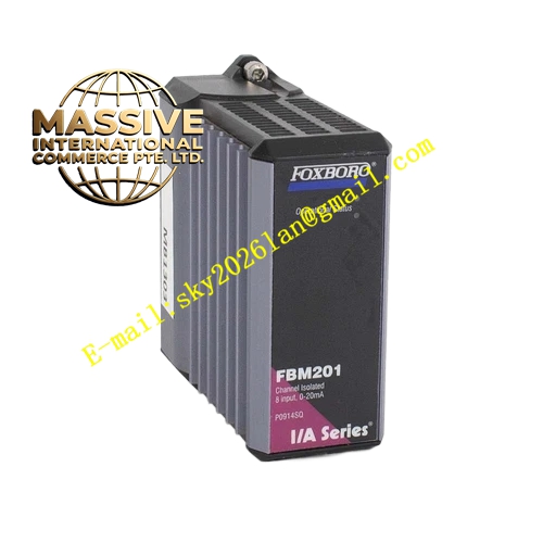
Description
Foxboro FBM09A 14A P0700AQ
Technical Specifications
- Module Model: FBM09A 14A (P0700AQ)
- Channel Configuration: 8 Discrete Inputs (DI) / 8 Discrete Outputs (DO)
- Signal Type: Dry contacts or low-voltage DC status
- Bus Interface: 2 Mbps Redundant HDLC Fieldbus
Functional Features
- Bidirectional Signal Processing: Consolidates 8 DI and 8 DO channels into a single module, significantly optimizing cabinet space and reducing wiring complexity.
- High Reliability Verification: Employs bit-by-bit matching technology to ensure absolute data accuracy and prevent erroneous information transfer.
- Complete Electrical Isolation: Full galvanic isolation between channels and the system bus effectively prevents ground loops and electrical interference.
- Online Diagnostics: Features built-in wire break detection, short circuit protection, and comprehensive module health reporting.
Application Scenarios
Ideal for simultaneous switch status monitoring and control output applications, such as driving solenoid valves, operating relays, and managing safety interlock signals.
Performance Parameters
- Response Time: Millisecond-level state capture and command execution for high-speed sequential control.
- Protection Rating: IP20
- Environmental Tolerance: ISA S71.04 G3 harsh environment compliant
Material Composition
Encased in an industrial-grade flame-retardant housing with high-reliability optocoupler and relay isolation circuits. Terminal blocks utilize premium conductive materials to ensure long-term durability and stable connections.
Structural Characteristics
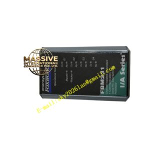
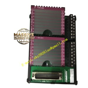
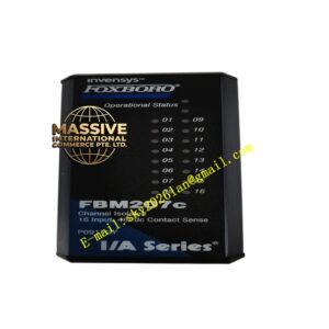
Standard FBM form factor featuring clear channel identification silk-screen printing and integrated status LEDs. A high-density precision backplane connector supports secure mounting and hot-swapping capabilities.
Working Principle
Input channels capture external contact or voltage signals via optocoupler isolation and level conversion, transforming them into digital logic levels for transmission over the redundant fieldbus. Output channels receive digital commands from the controller, isolate and amplify them to drive field actuators.
Installation Requirements
Insert securely into a compatible FBM baseplate. Field wiring must use shielded cables with the shield grounded at the cabinet side only to prevent electromagnetic interference.
Precautions for Use
Verify signal types and terminal definitions prior to wiring. Never short-circuit output loops. Always place the corresponding node in “Maintenance Mode” in the software before replacing the module.