Description
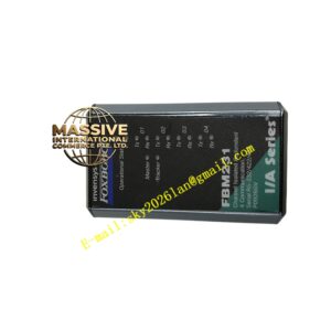
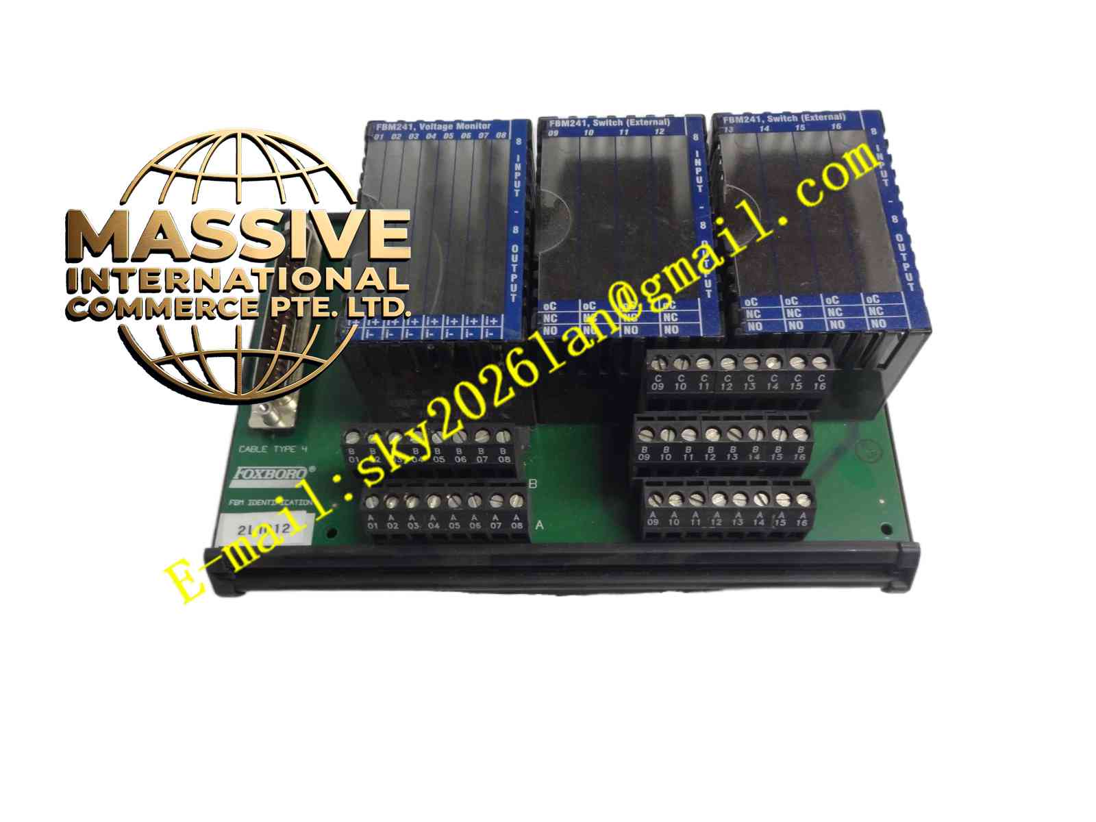
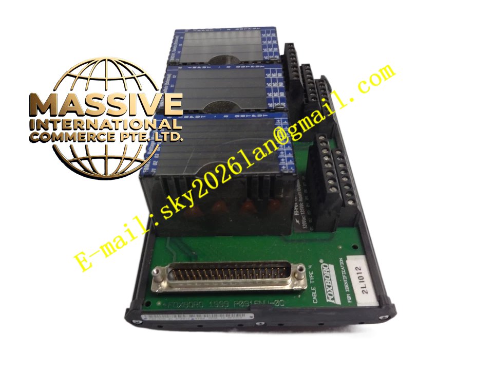
Foxboro FBM241
Technical Specifications
- Channel Configuration: 8 discrete inputs and 8 discrete outputs.
- Input Voltage: Supports 15-60 VDC, 120 VAC, 125 VDC, or 240 VAC.
- Output Voltage: Supports 15-60 VDC, 120 VAC, or 240 VAC.
- Output Current: Supports up to 5 A switching current depending on the specific sub-model and voltage.
- Fieldbus: Redundant 2 Mbps module fieldbus.
Functional Features
- Multi-Model Support: Offers FBM241/b/c/d types covering external power, internal power, and contact detection.
- Programmable Logic: Executes discrete I/O or ladder logic programs internally.
- Fail-Safe: Configurable input filter times, fail-safe fallback, and transient/continuous output modes.
- Channel Isolation: Each input and output channel is current-isolated for strong anti-interference capability.
Application Scenarios
Ideal for equipment start/stop control, valve status monitoring, alarm interlocks, and sequence control in chemical, pharmaceutical, power, and manufacturing industries.
Performance Parameters
- Isolation Voltage: Complete isolation between channels and channel-to-ground.
- Response Time: Configurable input filter times to adapt to field devices with varying response speeds.
- Pulse Output: Supports transient output configuration with customizable pulse intervals.
Material Composition
Constructed with a rugged extruded aluminum housing and strictly tested internal electronic components to ensure long-term stability in harsh industrial environments.
Structural Characteristics
- Hot-Swappable: Safely removes or replaces the module without removing field wiring.
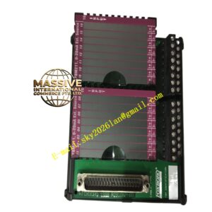
- Terminal Assemblies (TA): Uses dedicated DIN rail terminal assemblies providing relays, solid-state switches, and fuses.
- Visual Indicators: Front panel LEDs clearly indicate channel status and module health.
Working Principle
The FBM241 receives electrical signals from field sensors, performs signal conversion and isolation. For inputs, it converts them to digital states and uploads via the fieldbus. For outputs, it drives internal relays or solid-state switches based on controller commands to control external loads.
Installation Requirements
- Must be installed on a matching modular baseplate or DIN rail.
- Field I/O signals must be connected via designated terminal assemblies (TA).
- External excitation power must be connected correctly with attention to polarity.
Usage Precautions
- Strictly prohibited to exceed the module’s rated voltage and current limits.
- Confirm the sub-model (e.g., FBM241c) matches the original when replacing.
- Regularly inspect terminal assembly fuses and wiring tightness.