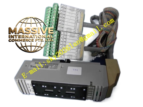
Description
Foxboro P0500SR
Technical Specifications
- Component Model: P0500SR (FBM07B)
- System Platform: Foxboro I/A Series DCS
- Function: High-Density Discrete DC Signal Conditioning and Conversion
- Communication: Standard Industrial Fieldbus Protocols
Functional Features
- Data Integrity Assurance: Employs bit-by-bit matching technology to guarantee accurate data transmission without corruption.
- High-Density Monitoring: 16 channels per component significantly reduces cabinet space and wiring costs.
- Software Integration: Seamlessly integrates with Foxboro InTouch and Wonderware System Platform.
- Intelligent Diagnostics: Built-in real-time diagnostics for wire break and short circuit detection.
Application Scenarios
Widely used for monitoring valve limit switches, relay contacts, pushbuttons, and safety interlock signals.
Performance Parameters
- Electrical Isolation: High-impedance isolation between channels and the bus.
- Response Time: Millisecond-level state capture for high-speed sequential control.
- Protection Rating: IP20
Material Composition
Industrial-grade flame-retardant housing with high-reliability optocoupler isolation circuits. Terminal blocks feature premium conductive materials.
Structural Characteristics
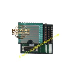
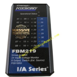
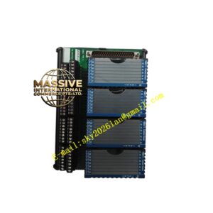
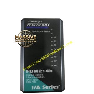
Standard fieldbus module design with clear channel labeling and LED indicators. Secure backplane connector ensures tight mechanical and electrical coupling.
Working Principle
External DC signals or contact closures pass through optocoupler isolation and level conversion, converting to digital logic levels for redundant fieldbus transmission.
Installation Requirements
Mount on a compatible FBM baseplate. Use shielded cables with cabinet-side single-point grounding.
Precautions for Use
Verify signal types and terminal definitions. Never exceed rated voltage limits. Disable corresponding node in software before replacement.