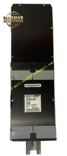
Description
Foxboro PO926TP
Technical Specifications
- Product Type: Power Entry Terminal Block Rail.
- System Compatibility: Foxboro I/A Series DCS.
- Function: Power distribution and field wiring termination.
- Mounting Style: Standard DIN rail or backplane mounting.
Functional Features
- Secure Power Distribution: Provides a centralized and safe point for distributing power to multiple Field Bus Modules (FBMs).
- Organized Wiring: Simplifies field wiring and maintenance with clearly labeled terminal blocks.
- High Current Capacity: Designed to handle the cumulative current load of multiple connected modules safely.
Application Scenarios
Used in all Foxboro I/A Series control stations and field enclosures where centralized power entry and distribution to I/O modules are required.
Performance Parameters
- Electrical Rating: Rated for standard industrial control voltages and high continuous current loads.
- Dielectric Strength: High insulation resistance to prevent short circuits and ensure operator safety.
Material Composition
Constructed with high-grade, flame-retardant thermoplastic housing and high-conductivity copper alloy terminal contacts to ensure low resistance and long-term reliability.
Structural Characteristics
- Compact Layout: Space-efficient design for high-density control panels.
- Tool-Actuated Clamps: Allows for secure wire termination without damaging the conductor.
- Visual Identification: Color-coded or clearly marked sections for power, ground, and signal differentiation.
Working Principle
The PO926TP acts as a passive electrical distribution node. Incoming main power is connected to the primary input terminals and internally routed to multiple output terminal blocks, which are then wired to the corresponding power pins of the FBM modules.
Installation Requirements
- Must be securely mounted on a standard DIN rail or dedicated backplane.
- Torque terminal screws to the manufacturer’s specified value to prevent hot spots.
- Ensure proper wire sizing to handle the maximum expected current without voltage drop.
Usage Precautions
- Always de-energize the system before performing wiring or maintenance.
- Regularly inspect terminals for signs of overheating, corrosion, or loose connections.
- Do not exceed the maximum rated current per terminal block.