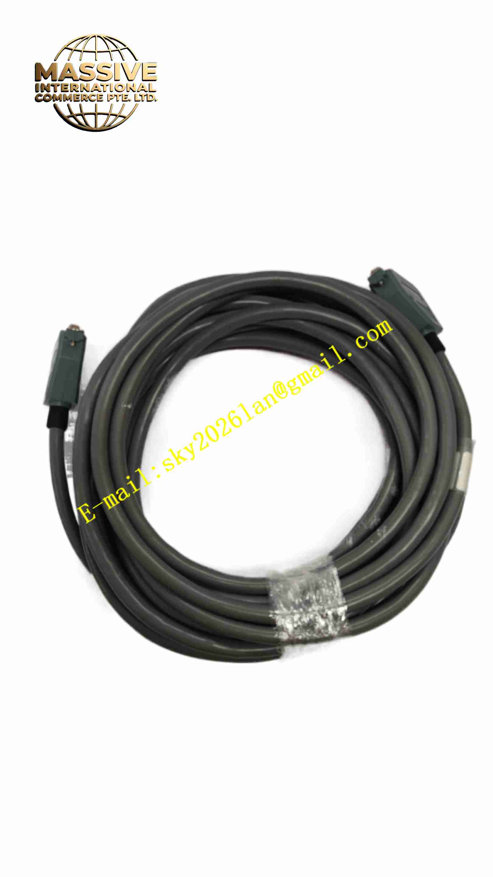
Description
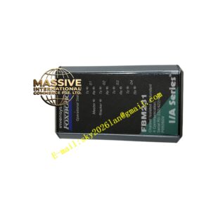
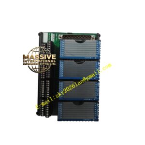
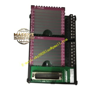
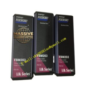
FOXBORO RH100CP Relay Module
Technical Specifications Model: RH100CP Brand: Foxboro Power Supply: Module bus power from DCS backplane Output Type: Potential-free mechanical relay contact Communication: DCS internal backplane bus Operating Temperature: 0 ℃ ~ +60 ℃ Storage Temperature: -40 ℃ ~ +85 ℃ Relative Humidity: 5% ~ 90%, non-condensing Mounting: DCS rack slot installation Protection Grade: IP20 Contact Rating: Rated voltage and current for relay contact
Functional Features Receives digital control command from Foxboro DCS controller through backplane bus. Built-in mechanical relay provides potential-free contact output to switch field equipment circuit. Relay contact state feedback circuit returns contact status to DCS system. Onboard self-diagnosis monitors module power supply and relay drive hardware state. Front panel LED indicators show module running state and relay on-off status. Overcurrent protection for relay drive circuit. Supports hot swap in compatible Foxboro DCS rack system. Fault diagnostic data uploaded to DCS host station.
Application Scenarios Chemical process plant control system, power plant auxiliary equipment interlock control, oil and gas pipeline valve control, water treatment plant equipment start-stop control, refining plant safety interlock system.
Performance Parameters Mechanical relay contact switches rated load reliably within service life cycle. State feedback circuit accurately returns relay contact status to DCS controller. Self-diagnosis circuit detects module power failure and drive circuit abnormality. Module maintains stable communication with DCS backplane bus under industrial electromagnetic environment. LED indicators reflect relay switching state synchronously. Hot swap function allows module replacement without shutting down whole DCS rack.
Material Composition Housing: Black flame-retardant plastic front panel and metal shielding frame. Main PCB: FR4 multi-layer printed circuit board with conformal protective coating. Core Electronic Components: Bus interface chip, relay drive IC, mechanical relay, feedback sampling circuit, EMC protection components, non-volatile memory. Connector: Gold-plated backplane edge connector and screw terminals for field wiring. Indicator Components: LED status indicators on front panel. Fasteners: Stainless steel screws and metal fixing brackets.
Structural Features Standard DCS rack card structure for installation in Foxboro control rack slot. Front panel equipped with LED indicators and module identification marking. Rear gold-plated edge connector mates with DCS rack backplane for power and bus communication. Field signal screw terminals located on front or rear side for field wiring connection. Metal shielding frame reduces electromagnetic interference. Internal circuit separates low-voltage DCS bus circuit and field relay contact circuit.
Working Principle The module obtains working power and DCS bus communication signal from DCS rack backplane. When DCS controller sends digital on/off command via backplane bus, onboard drive circuit energizes or de-energizes relay coil. Mechanical relay contact closes or opens to switch field equipment circuit. Contact feedback sampling circuit reads actual relay contact state and transmits status signal back to DCS controller through backplane bus. Self-diagnosis circuit continuously monitors module power and relay drive hardware. When fault occurs, fault LED activates and fault information is uploaded to DCS operator station.
Installation Requirements Cut off DCS rack power supply before inserting or removing module if hot swap is not supported by system configuration. Insert RH100CP module into designated empty DCS rack slot, lock front panel fasteners. Connect field load wiring to relay screw terminals strictly following wiring diagram. Install Foxboro DCS system software and complete module hardware identification. Set relay output logic parameters in DCS configuration software. Power on rack and test relay switching function. Keep ventilation path of DCS rack unobstructed.
Usage Precautions Do not exceed rated voltage and current of relay contact. Use external fuse for field load circuit protection. Keep field high-current wiring separated from DCS signal cables. Do not operate in environment with condensation, corrosive gas or conductive dust. Do not disassemble module housing without professional authorization. Check relay contact wear regularly for long-time frequent switching application. Cut off field load power before modifying field wiring.