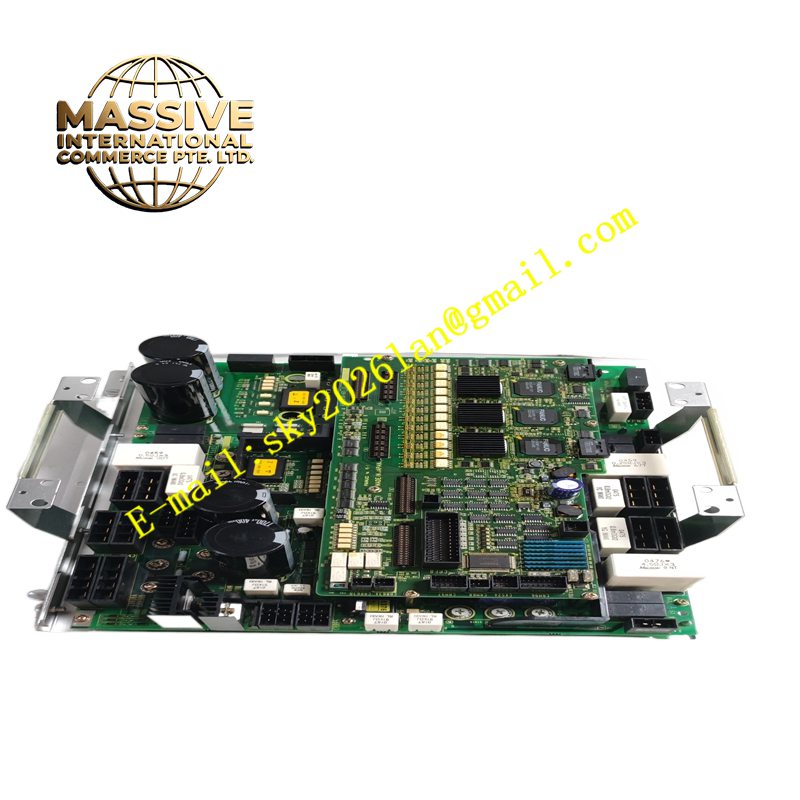
Description
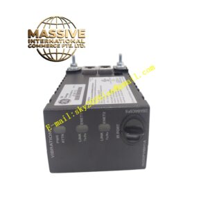
GE A06B-6107-H001
Technical Specifications DC bus power input; three-phase AC output for servo motor; serial encoder signal interface; built-in IGBT power stage; overcurrent, overvoltage and overtemperature protection; front panel status LED indicators; rack plug-in structure.
Functional Features Converts DC bus voltage into variable-frequency three-phase AC to drive servo motors. Compares encoder feedback position with CNC command and adjusts output current in real time. Triggers hardware protection and fault alarm upon overcurrent, overvoltage, overload or overheating. Communicates fault codes, current status and speed data to the CNC host. Supports dynamic brake function for rapid axis deceleration.
Application Scenarios CNC machine tool feed axis control, industrial robot axis drive, automated gantry and material handling servo axes matched with Fanuc CNC platforms.
Performance Parameters Fast current loop response; high bandwidth speed regulation; accurate torque control; reliable fault detection with fast protection action.
Material Composition Main circuit board is high-current FR-4 multilayer PCB; power switching components are industrial IGBT modules; internal heat sink is extruded aluminum alloy; front panel is coated metal; terminal connectors are nickel-plated copper alloy.
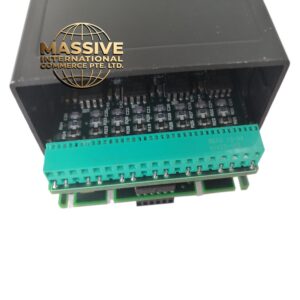
Structural Characteristics Rectangular rack plug-in module; rear bus connector for DC power and CNC backplane communication; front panel with status LEDs and test terminals; finned heat sink for passive thermal dissipation; internal power board and control board stacked assembly.
Working Principle DC bus power enters the IGBT power module. The onboard control circuit receives position commands from the CNC and reads motor encoder feedback. The control algorithm calculates required torque and outputs PWM signals to drive the IGBT bridge, generating three-phase AC for the servo motor. Built-in monitoring circuits sample current, voltage and temperature and shut down output when thresholds exceed limits.
Installation Requirements Insert the amplifier into the designated slot of the Fanuc drive rack and lock the fixing levers. Connect DC bus terminals, motor power cable and encoder feedback cable according to schematic diagrams. Maintain required air clearance around heat sink for ventilation. Complete axis parameter setting and servo tuning after power on.
Precautions for Use Confirm DC bus voltage matches the amplifier rating before power application. Do not touch power terminals for a waiting period after power cut to avoid residual capacitor charge. Keep metal debris away from the rack interior. Replace the unit immediately if repeated power stage faults occur.