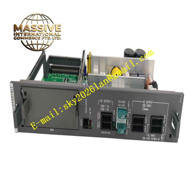
Description
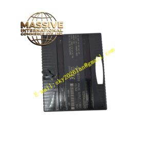
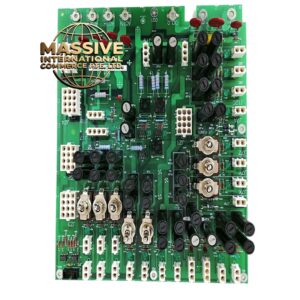
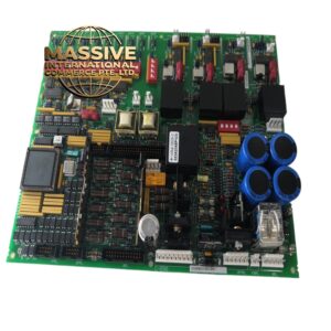
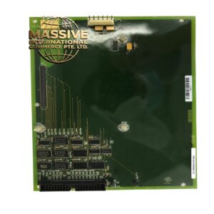
GE A16B-2203-0910
Technical Specifications AC input range 200-240V; multiple DC output rails for CNC logic circuits; built-in input EMI filter; overvoltage, overcurrent and overtemperature protection; rack plug-in structure; status indicator circuits.
Functional Features Filters and rectifies AC mains power into primary DC bus. Generates multiple isolated low-voltage DC outputs for digital logic and analog circuits of the control system. Activates protection circuits to shut down output during overload, short circuit or overheating. Provides power good status signal to the CNC main controller.
Application Scenarios Fanuc robot controller racks, POWERMATE CNC cabinets, legacy series CNC system control racks.
Performance Parameters Tight output voltage regulation; low ripple noise on DC outputs; fast protection response under short-circuit fault; stable output within rated ambient temperature range.
Material Composition PCB substrate is FR-4 flame-retardant multilayer board; main power switching components are high-voltage power semiconductors; high-frequency transformer and electrolytic capacitors meet industrial long-life standard; connector contacts are gold-plated copper.
Structural Characteristics Plug-in board assembly with metal front bezel; AC input terminal block on front panel; DC power output edge connectors mating with system backplane; large electrolytic capacitors and power components arranged on the PCB with insulation barriers.
Working Principle AC input passes through EMI filter and bridge rectifier to form high-voltage DC bus. The PWM control chip drives power switching devices and high-frequency transformer to step down voltage. Secondary rectifier and filter circuits produce each required low-voltage DC rail. Monitoring circuits continuously sample output voltage, output current and component temperature and trigger shutdown when limits exceed.
Installation Requirements Power off the entire control rack before removing or inserting this power board. Secure the front panel fixing screws after insertion. Verify AC input wiring matches terminal marking. Check all DC output voltages before loading the rack with other boards.
Precautions for Use Allow sufficient discharge time after power cut before touching internal power components. Do not operate the board with missing or damaged insulation barriers. Replace aged electrolytic capacitors during overhaul cycles.