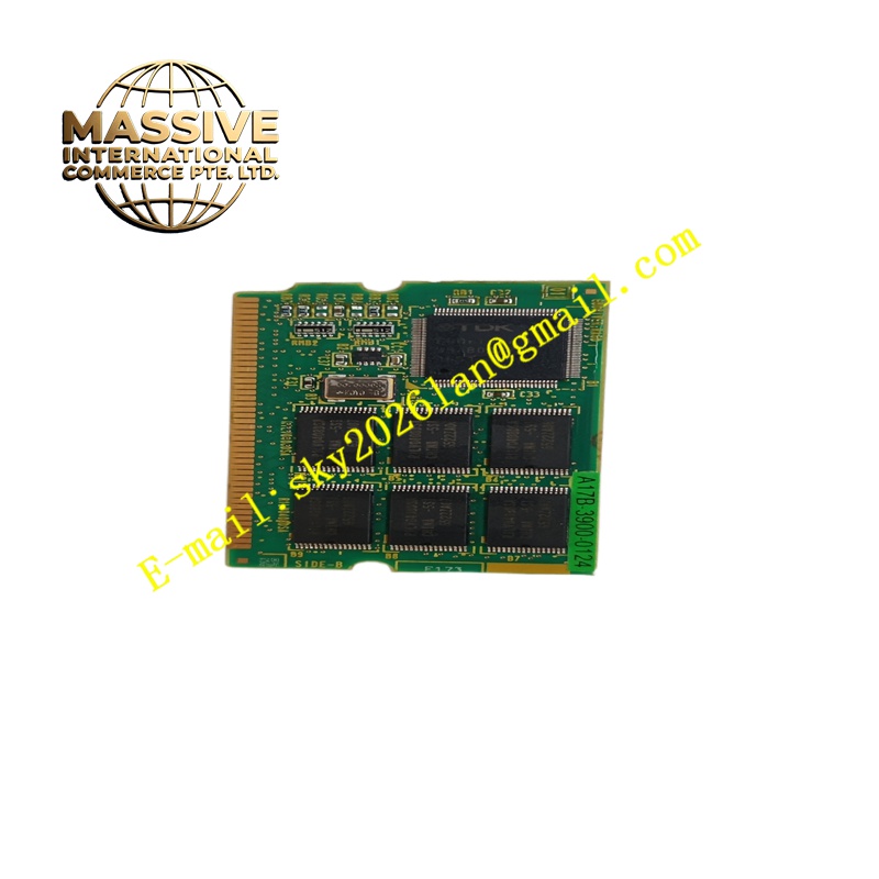
Description
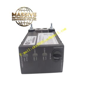
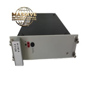
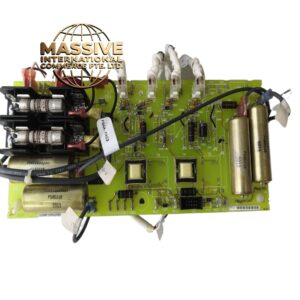
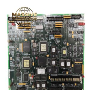
GE A17B-3900-0124
Technical Specifications Three-phase or single-phase AC input; high-voltage DC bus output for servo drives; auxiliary 24V DC logic power; inrush current suppression circuit; bus overvoltage and ground fault protection; rack plug-in assembly.
Functional Features Rectifies AC input to form the main DC bus shared by multiple servo amplifiers. Limits inrush charging current for bulk bus capacitors during power-up. Provides auxiliary regulated DC power for control and detection circuits. Detects bus overvoltage, ground leakage and input phase loss and triggers fault shutdown. Reports power unit fault status to the CNC or robot main controller.
Application Scenarios Fanuc Alpha series servo drive racks, R-30iA robot controller power racks, high-power CNC machine tool drive cabinets.
Performance Parameters High continuous bus power capacity; controlled inrush current at power on; fast overvoltage protection response; stable auxiliary logic voltage under dynamic servo load fluctuation.
Material Composition Assembly housing is coated steel sheet; main power PCB uses thick copper FR-4 substrate; power rectifier modules and IGBTs are high-current industrial grade; bus capacitors are long-life industrial electrolytic type; terminal blocks use nickel-plated copper conductors.
Structural Characteristics Metal enclosed rack plug-in unit; AC input terminals and status indicators on front panel; internal partition separating high-voltage bus area and low-voltage control area; rear bus connectors mating with drive rack backplane; built-in discharge resistor for bus capacitors.
Working Principle AC input flows through EMI filter and inrush current limiting circuit. The rectifier stage converts alternating current into DC bus voltage stored on bulk capacitors. Auxiliary switching converter taps power from the input side to generate low-voltage DC for control logic. Voltage and current monitoring circuits continuously sample bus conditions and shut down input power when fault thresholds trigger.
Installation Requirements Install the unit into the dedicated power slot of the Fanuc drive rack. Connect three-phase AC input wiring strictly following phase marking. Confirm bus polarity before connecting servo amplifier modules. Test input phase loss and overvoltage protection function during commissioning.
Precautions for Use Bus capacitors hold dangerous high voltage long after power removal. Wait for the specified discharge interval before opening the unit cover. Do not bypass the inrush current limiting resistor. Do not operate the unit without proper protective earth connection.