Description
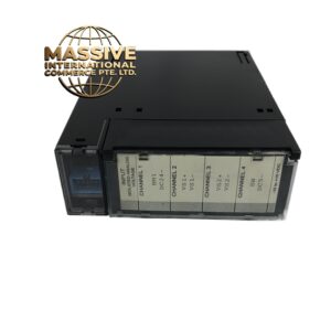
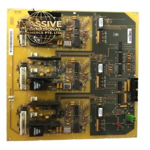
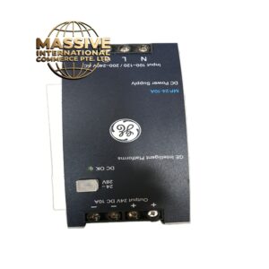
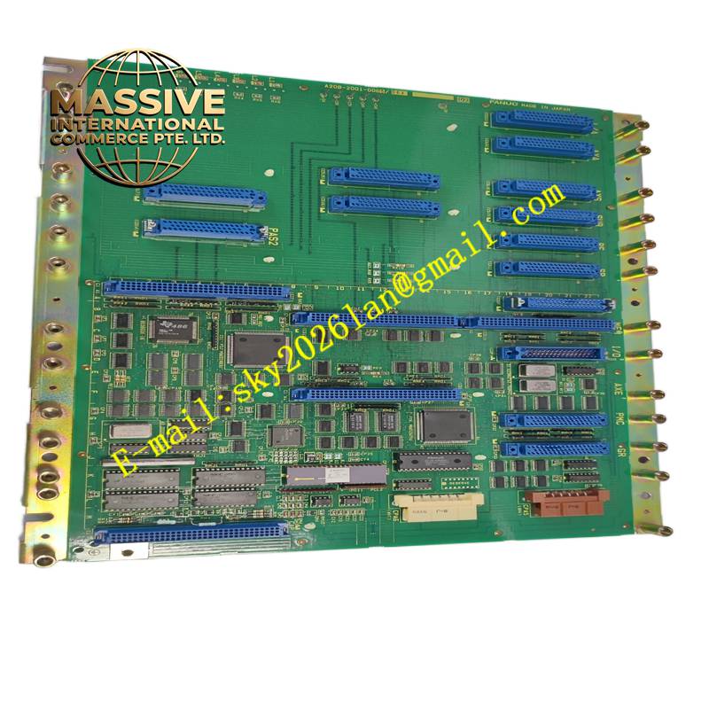
GE A20B-2001-006506A
Technical Specifications Serial encoder signal receiving circuit; analog current sampling and amplification; high-speed ADC conversion; optical isolation for feedback signals; edge connector for mating with servo main board; small form factor daughter card.
Functional Features Receives and decodes serial encoder data transmitted from the servo motor. Samples motor phase current through current sensors and converts analog signals into digital values for the control DSP. Filters and isolates feedback signals to suppress industrial noise. Transmits fault flags and sampled data to the main servo control board.
Application Scenarios Fanuc Alpha servo amplifier internal sub-assemblies for CNC machine feed axes and robot joint axes.
Performance Parameters High sampling rate for phase current; low signal latency for encoder data; high common-mode noise rejection; stable signal conversion under rapid current fluctuation.
Material Composition PCB substrate is thin FR-4 flame-retardant material; signal processing chips are high-speed industrial semiconductors; optocoupler devices provide galvanic isolation; edge connector fingers are gold-plated copper alloy.
Structural Characteristics Small rectangular daughter PCB; edge card connector on one side to plug into the main servo amplifier board; surface-mounted signal conditioning, isolation and sampling components; silk screen marking for signal nets.
Working Principle Encoder differential signals from the motor cable enter the receiving circuit of this daughter board. Current transducers produce analog voltage proportional to motor winding current, which the board amplifies and sends to analog-to-digital converters. Isolation circuits break ground loops between motor side and control DSP side. Sampled digital data is sent through the edge connector to the main control DSP for servo algorithm calculation.
Installation Requirements Power down the servo amplifier before disassembly. Align the edge connector and insert the daughter board fully into the matching socket on the main power board. Inspect connector fingers for contamination or oxidation before assembly. Reassemble the amplifier housing and perform servo axis test after power restoration.
Precautions for Use Use anti-static protection during handling. Do not pull the board by the PCB body to avoid bending traces. Do not apply voltage to the encoder input terminals without matched current-limiting circuits.