Description
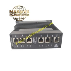
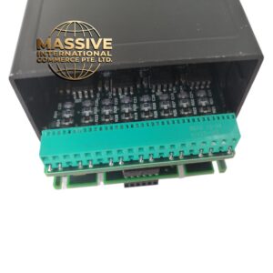
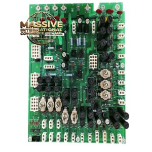
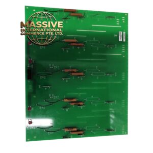
GE A20B-3400-0020
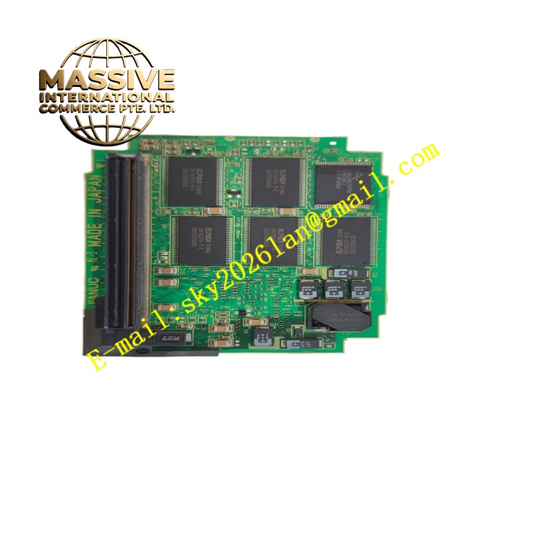
Technical Specifications Onboard SDRAM and flash memory chips; memory bus interface matching robot main CPU; data parity detection circuit; edge connector for CPU board socket; 24V low-voltage logic power.
Functional Features Expands system working memory for robot operating system and motion interpolation computation. Stores user teach programs, position registers, tool frames and system configuration data in non-volatile flash area. Executes data parity check to detect memory read-write errors. Transfers address and data signals between memory chips and main CPU over the local bus.
Application Scenarios Fanuc R-30iA robot controllers for welding, handling and assembly robots requiring large program storage and complex motion calculation.
Performance Parameters High-speed synchronous memory access; low data access latency; parity error reporting for memory faults; stable data retention in flash area after power loss.
Material Composition PCB substrate is FR-4 multilayer flame-retardant board; memory chips are industrial wide-temperature grade; bus connector contacts are gold-plated copper alloy; passive components are high-reliability ceramic capacitors and resistors.
Structural Characteristics Compact rectangular daughter board; edge connector at one end for insertion into the main CPU board; memory chips and support circuits densely arranged on PCB surface; mounting locating holes for mechanical fixation.
Working Principle The main CPU sends address, read and write commands over the memory bus to this expansion board. SDRAM chips provide fast temporary working space for real-time robot calculation. Flash chips retain user programs and parameters when controller power shuts down. Parity circuits verify each data word and send fault alerts to the system if bit errors are detected.
Installation Requirements Power off the robot controller and discharge internal power supplies. Locate the dedicated memory expansion socket on the main CPU board. Insert the board straight and fully seat the edge connector. Lock the retention clip and reassemble the controller chassis. Enter system maintenance screen to verify expanded memory capacity after power on.
Precautions for Use Static discharge can damage memory chips, so anti-static measures are mandatory. Confirm robot system software version supports this memory board before installation. Back up all robot programs and parameters before replacement.