Description
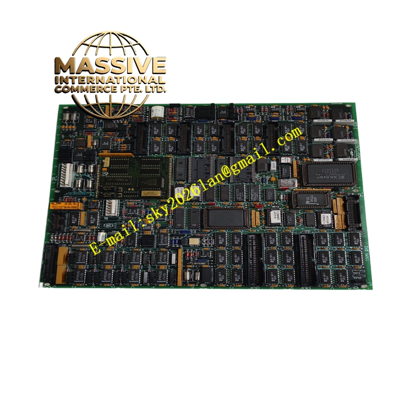
GE DS200TCCAG2AJB
Technical Specifications
- Series: GE Mark V Speedtronic
- Microprocessor: 16-bit 80196 microprocessor
- Memory: Multiple EPROM modules containing firmware and instruction code
- Connectors: 2PL, 3PL, JAA, JBB, JCC, JDD, JAR/S/T, JC, and JEE
- Hardware Jumpers: J1 (RS232 port), JP2 (oscillator disable), JP3 (factory testing)
Functional Features
- Processes 4-20 mA inputs and outputs, RTD inputs, thermocouple inputs, and shaft voltage/current inputs.
- Calculates cold junction compensation for accurate thermocouple temperature readings.
- Stimulates RTDs and measures voltage shifts to calibrate and scale temperature signals.
- Routes conditioned signals to the COREBUS via the 3PL data bus connector.
Application Scenarios
Deployed in gas turbine control management systems within power generation plants to monitor critical operational parameters and maintain safe, efficient turbine operation.
Performance Parameters
- High-speed signal conditioning with deterministic processing.
- Supports multiple signal types simultaneously without cross-interference.
Material Composition
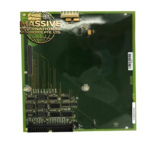
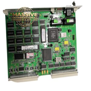
Industrial-grade printed circuit board (PCB) featuring a normal protective coating, high-reliability 80196 microprocessor, and precision analog components.
Structural Characteristics
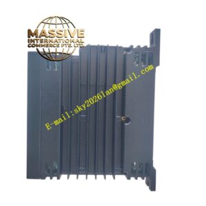
Standard Mark V board form factor equipped with two 50-pin connectors (JCC and JDD), a visible side-view LED indicator, and multiple specialized interface ports.
Working Principle
The 80196 microprocessor executes code from the EPROM modules to acquire raw analog signals from terminal boards, applies mathematical scaling and compensation, and transmits the digital values to the I/O Engine.
Installation Requirements
- Power to the R5 core must be completely removed before handling.
- EPROM modules must be carefully transferred from the old board to the new board using a flathead screwdriver to gently rock the chips free.
- Ensure all ribbon cables are seated firmly in their respective connectors.
Usage Precautions
- Always wear an ESD preventive wrist strap when handling the board or EPROM modules.
- Store removed EPROM modules in static protective bags immediately.
- Verify that the jumper settings match the system configuration before applying power.