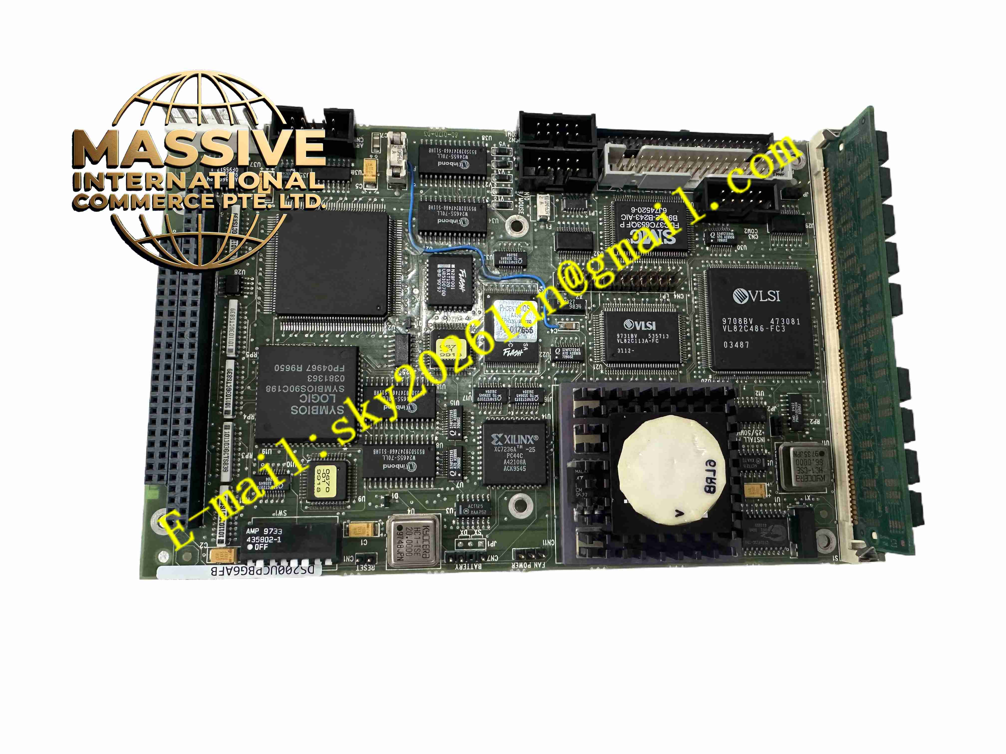
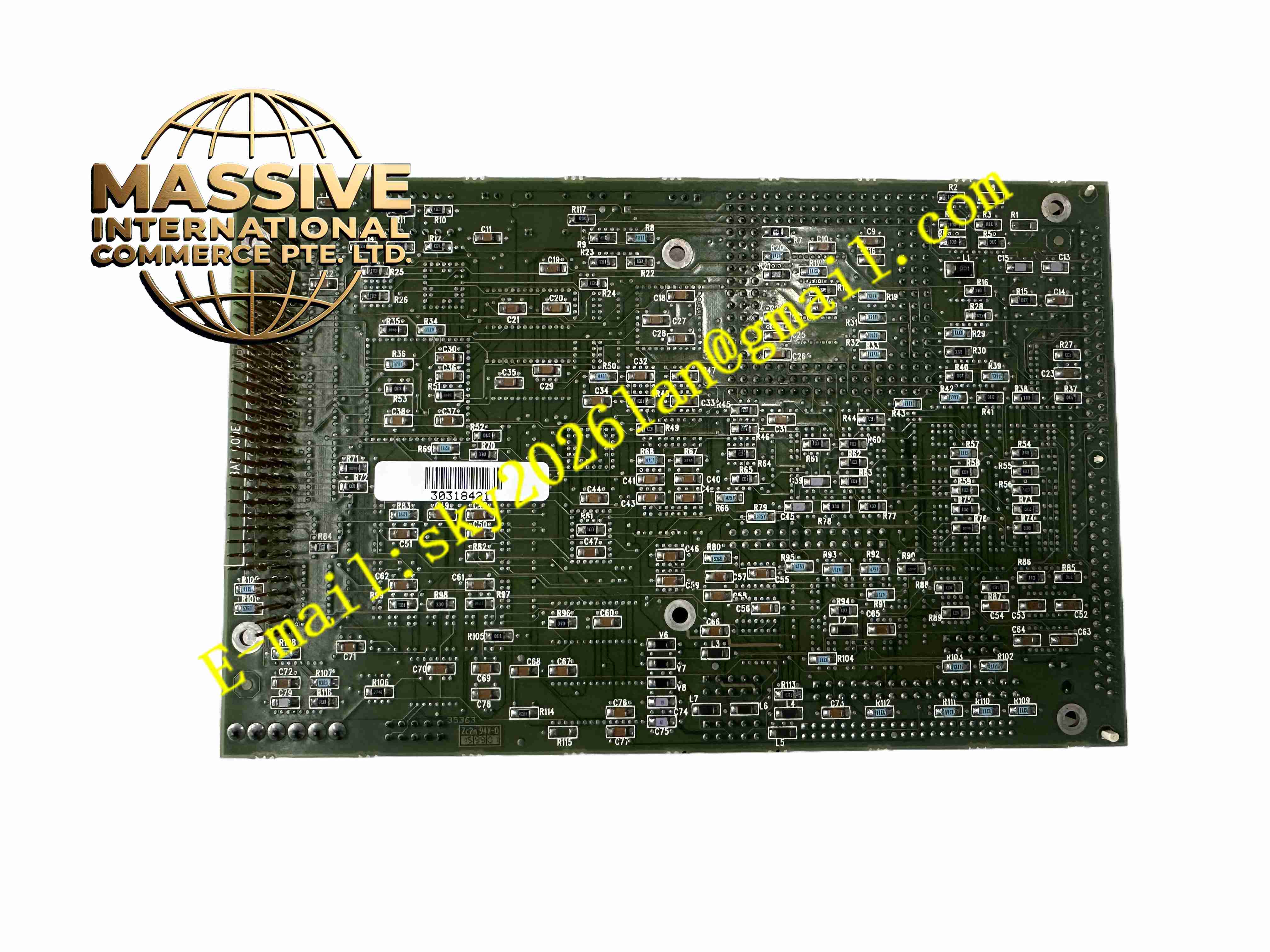
Description
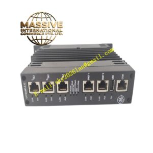
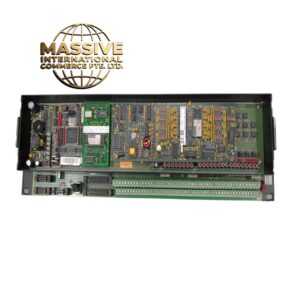
GE DS200UCPBG6AFB
Technical Specifications:
- Processor: Intel 80486DX real-time microprocessor
- Memory: SIMM socket for DRAM, EPROM/flash for firmware storage
- Communication Interfaces: Dual RS-232 service ports, ARCNET, COREBUS backplane bus
- Power Supply: +5 VDC supplied from Mark V rack backplane
- Data Packet Rate: 100 Hz fast packets for critical real-time signals
- DIP Switches & Jumpers: Onboard DIP switches and jumpers for COREBUS address and bus speed configuration
- Operating Temperature: 0°C to +60°C
- Storage Temperature: -40°C to +85°C
- Front Panel: LED status indicators for power, bus activity and fault
Function Features:
- Real-time execution of turbine control, protection and sequencing algorithms
- I/O data packaging and transmission across COREBUS to main control processors
- ARCNET communication for rack-wide system data exchange
- Dual RS-232 serial ports for local service, commissioning and troubleshooting
- Onboard hardware DIP switches to set rack address and bus parameters
- Continuous system self-diagnosis and fault status reporting
- Support redundant rack installation for high availability turbine control
- Non-volatile firmware storage to retain control logic after power loss
Application Scenarios:
- GE Mark V Speedtronic gas turbine control systems
- Steam turbine power generation control cabinets
- Combined cycle power plant turbine control racks
- Power plant turbine control system spare replacement and maintenance
Material Composition:
- Substrate: Multilayer FR4 fiberglass printed circuit board
- Core Components: Intel 80486DX processor, DRAM SIMM, EPROM flash chips, ARCNET controller
- Connectors: Gold-plated board-to-board daughterboard connectors for STCA chassis mounting
- Passive Components: High-temperature industrial capacitors, resistors and transient suppression devices
- Solder: High-temperature lead-free solder for power cabinet environment
Structural Features:
- Daughterboard form factor, mounted onto STCA switchable terminal card assembly
- Edge gold-plated connectors to interface with rack backplane
- Front panel mounted LED status indicators for visual diagnostics
- Compact card design to fit standard Mark V rack slot
- Internal metal shielding for electromagnetic noise suppression
Working Principle: The board receives power from the rack backplane. The 80486DX processor runs turbine control firmware stored in EPROM flash. It collects I/O data from the STCA terminal assembly, packages data into fast and slow packets and transmits over COREBUS to main Mark V control processors. ARCNET provides rack-level inter-board communication. RS232 ports allow service tool connection for parameter viewing and fault diagnosis. DIP switches set unique rack address for multi-rack turbine systems.
Installation Requirements:
- Install daughterboard onto STCA assembly inside the Mark V turbine control rack
- Maintain cabinet air conditioning to keep temperature within rated operating range
- Handle board with anti-static wristband during installation
- Ensure gold-plated connectors are fully seated and free of contamination
- Follow rack grounding specifications for protective earth connection
- Keep high voltage wiring separated from low voltage control rack
Usage Notes:
- Power down entire turbine control rack before removing or inserting the board
- Avoid touching gold-plated connector pins directly with bare fingers
- Record DIP switch and jumper settings before board removal
- Inspect PCB surface for dust and corrosion periodically during outage maintenance
- Verify firmware revision matches turbine project configuration after replacement