Description
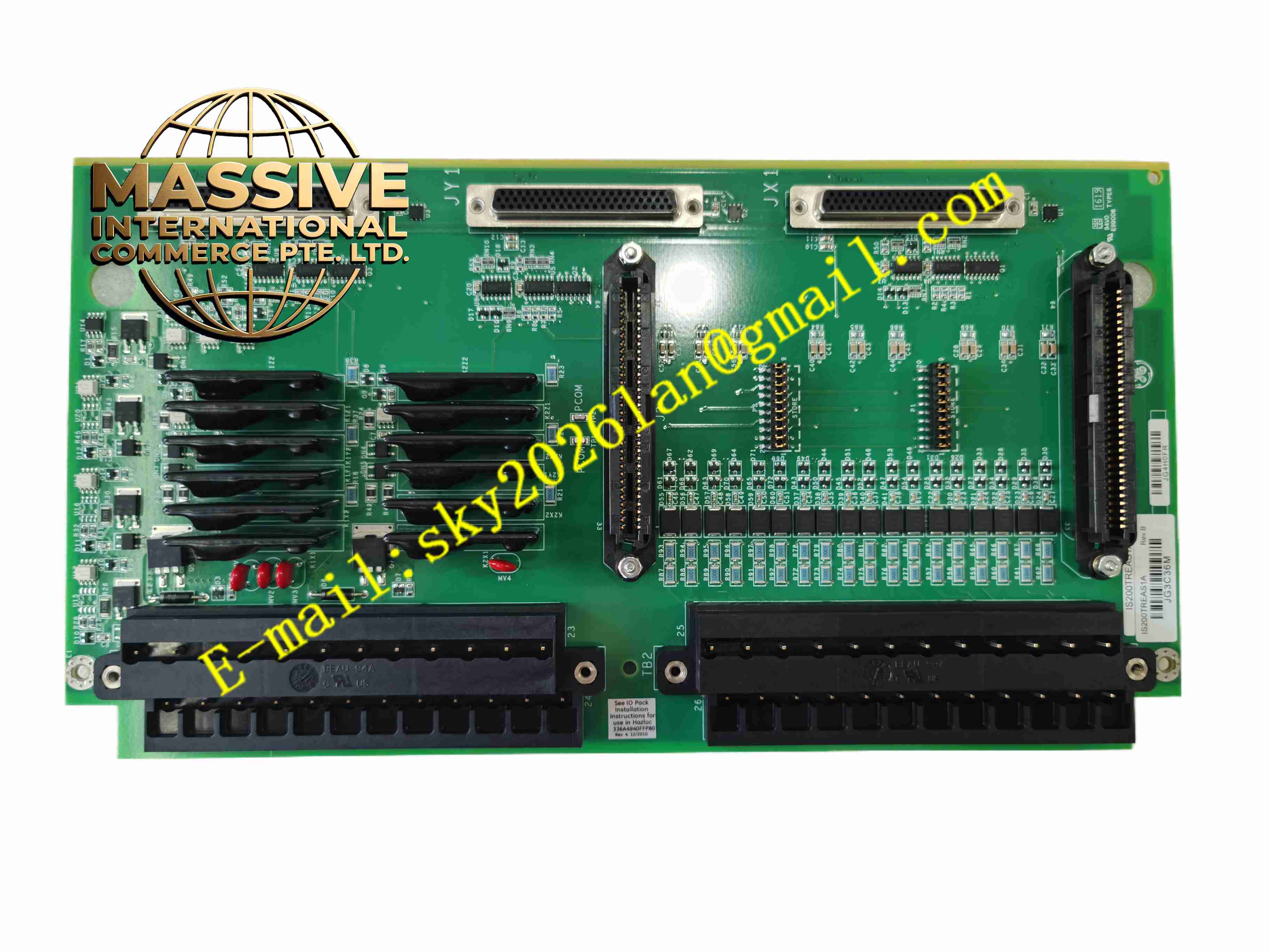
GE IS200TREAS1A
Technical Specifications 3 digital input channels; 2 trip output channels; MPU pulse input frequency range up to 2kHz; MPU input sensitivity 27mV; Board power supply from Mark VIe backplane; Surface mount component technology; Board dimension 330mm ×178mm.
Functional Features Signal filtering and noise suppression for turbine speed MPU signals; Isolation and conditioning for emergency trip discrete input; Relay-based trip output for turbine safety shut-down; On-board hardware self-check during power-up; Fault status feedback to Mark VIe controller; Surge protection for field sensor wiring; High-reliability safety circuit design for turbine protection.
Application Scenarios Aeroderivative gas turbine control system; Power plant gas turbine emergency trip protection; Industrial gas turbine generator Mark VIe control cabinet.
Performance Parameters Operating temperature range 0℃ to +65℃; Storage temperature -40℃ to +85℃; Relative humidity 5% to 95% no condensation; Vibration resistance meets power generation control standard; Conformal coating option available for harsh environment.
Material Composition Multi-layer glass fiber PCB board; Gold-plated edge connector for backplane connection; Signal isolation optocouplers; Surge suppression TVS diodes; Electromechanical trip relays; Surface mount resistors and capacitors; Screw terminal blocks.
Structural Characteristics Horizontal plug-in board for Mark VIe I/O rack; Edge gold finger for backplane connection; Front side terminal blocks for field sensor wiring; Metal mounting latch to lock board into rack; Component area separated into signal input and trip output zones.
Working Principle Field MPU speed pulse and trip contact signals enter through terminal block. The on-board circuit filters interference noise and converts raw signals into standard logic levels. Processed signals transfer to Mark VIe backplane for turbine controller. When emergency trip condition triggers, the board activates trip relay output to cut off fuel supply of gas turbine. Built-in diagnostic circuit monitors board hardware continuously and sends fault alarm to controller.
Installation Requirements Cut off rack power before inserting board. Wear anti-static wristband during handling. Insert board smoothly into empty Mark VIe rack slot and fasten mounting latch. Connect field sensor wiring to terminal blocks. Power on and execute Mark VIe system hardware diagnosis, verify trip signal loop. Ensure cabinet reliable protective earthing.
Usage Notes Static protection must be applied at all times during handling. Backup turbine control logic before board replacement. Do not modify onboard circuit components. Clean PCB surface dust periodically. Store spare board in anti-static bag under dry condition.