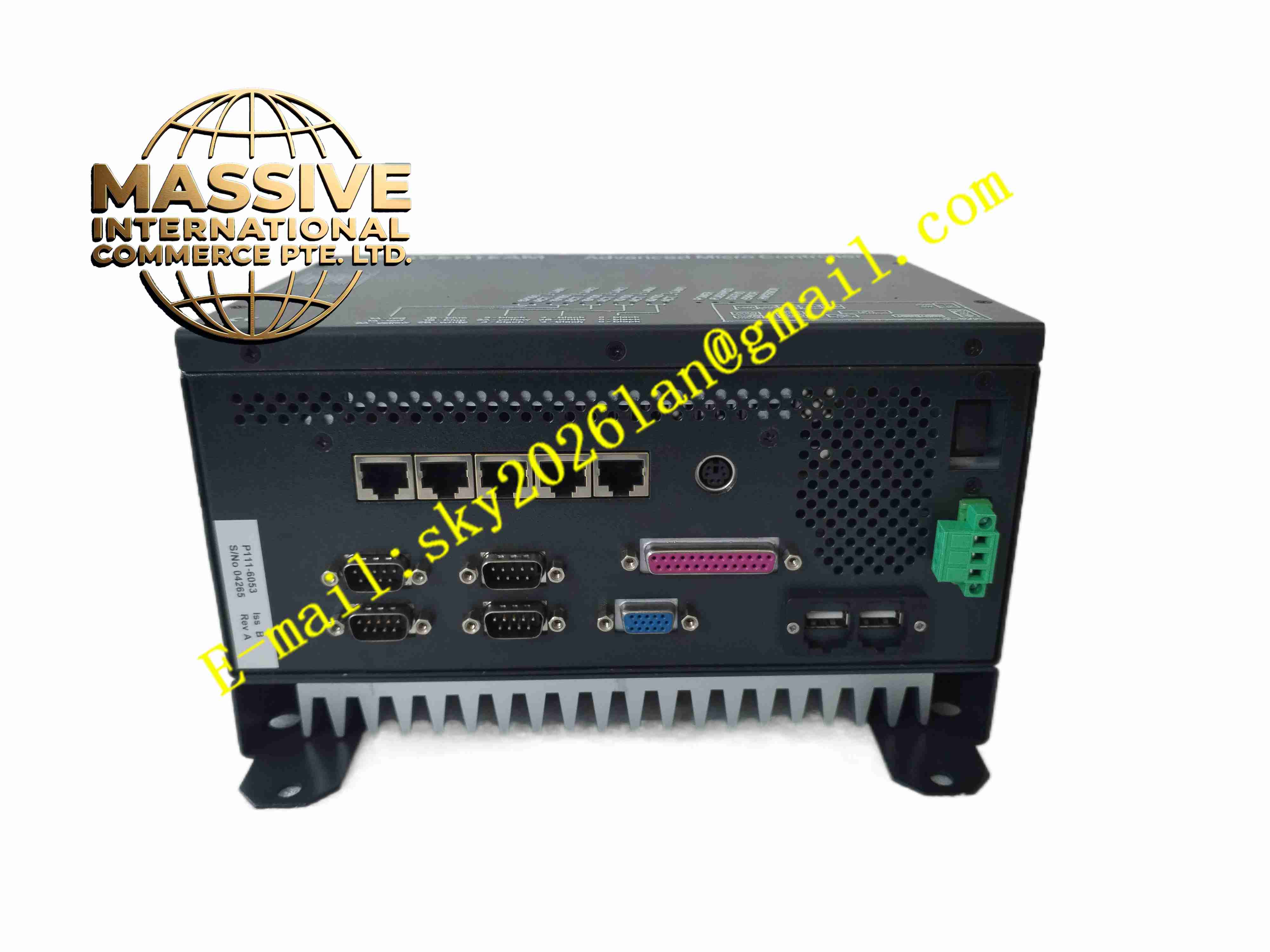
Description
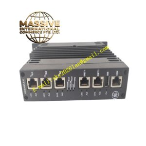
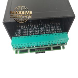
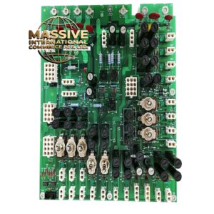
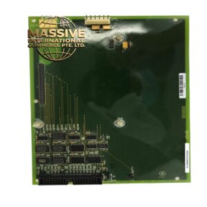
GE P111-6053
Technical Specifications
- Product type: Industrial communication interface board
- Communication ports: RS232/RS485
- Bus protocol: Modbus RTU
- Baud rate: 300 to 19200 bps
- Isolation: 500 V channel isolation
- Supply: Backplane/motherboard 5 V DC
- Operating temperature: 0 °C to +60 °C
- Storage temperature: -20 °C to +70 °C
- Relative humidity: 5 % to 95 %, non-condensing
- Protection rating: IP20
- Installation: Plug-in card
- LEDs: TX/RX status
Functional Features
- Multi-channel industrial communication expansion
- RS232 and RS485 dual mode
- Modbus RTU protocol support
- Channel electrical isolation
- Front panel LEDs indicate communication status
- Industrial-grade components
- Withstands strong electromagnetic environment
- Plug-and-play driver support
- Continuous long-term operation
- Modular design
Application Scenarios
- GE PLC to upper computer communication
- Variable frequency drive and instrument Modbus access
- Water treatment plant remote communication
- Manufacturing equipment networking
- Power RTU data acquisition
Materials and Construction
- PCB: FR4 board
- Communication components: RS232/RS485 transceivers, optocouplers
- Connector: Backplane connector, DB9
- Passive components: TVS diodes, resistors, capacitors
- Front panel: Metal panel
Structural Features
- Plug-in structure in rack or PC slot
- Front panel DB9 and LEDs
- Internal communication isolation area
- Backplane gold fingers
- Card locking mechanism
- Metal shielding
Working Principle The CPU reads data through the backplane, packages it as serial frames, and sends it to external devices through isolated transceivers. External serial signals are isolated and converted to digital values, uploaded to the CPU via the backplane. LEDs indicate transmit/receive status.
Installation Requirements
- Insert into slot with power off
- Shielded serial cable
- 120 Ω termination resistor at RS485 bus end
- Grounding
- Temperature 0 °C to +60 °C
- Install driver and configure parameters after power-up
- Ensure no duplicate addresses
Precautions
- Power off before insertion/removal
- RS485 A/B polarity must not be reversed
- Baud rate must match both ends
- Store spares in anti-static packaging
- Wear ESD wrist strap
- Check termination resistor on communication fault