Description
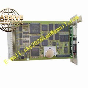
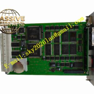
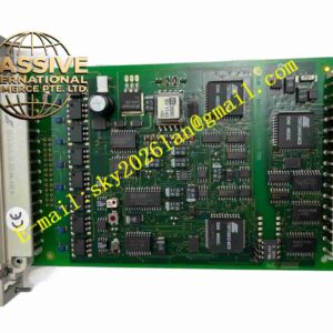
HIMA K9203 996920302
Technical Specifications
- Module type: Safety PLC communication module
- Communication interface: Ethernet 10/100 Mbps
- Protocol: Modbus TCP, TCP/IP
- Node address: Software-configured IP
- Supply: Rack backplane DC5V
- Isolation: Ethernet interface isolated from backplane
- Temperature: -20 °C to +70 °C
- Storage: -40 °C to +85 °C
- Humidity: 5 % to 95 %, non-condensing
- Protection: IP20
- Installation: Eurocard plug-in
- Safety level: SIL3
- LEDs: Link, Act, power, fault
Functional Features
- Ethernet to upper SCADA/DCS
- Modbus TCP read/write safety system data
- Secure communication with CRC-protected frames
- Front panel LEDs for Link, Act, and fault
- Ethernet optically isolated from backplane
- Dual-channel redundant communication support
- IP, subnet mask, gateway software configurable
- Automatic retry and alarm on communication loss
- Industrial wide-temperature design
- Data mapping safety with HIMA safety CPU
Application Scenarios
- Petrochemical SIS to upper DCS/Modbus TCP communication
- Power plant ESD to SCADA data upload
- Offshore platform safety controller to central room communication
- Chemical plant safety interlock centralized monitoring
- HIMA HIMax integration with plant Ethernet
Materials and Construction
- Front panel: Flame-retardant engineering plastic
- PCB: FR4 multilayer board with conformal coating
- Communication: Ethernet PHY, isolation transformer
- Connector: RJ45, gold-plated Eurocard backplane
- Passive components: Metal film resistors, ceramic capacitors
- Panel: Metal shielding
Structural Features
- Eurocard plug-in in HIMA rack communication slot
- Front panel RJ45 and status LEDs
- Board partitions between Ethernet PHY, protocol processor, and backplane
- Network transformer isolating Ethernet from digital circuits
- Card locking mechanism
- Metal panel shielding
Working Principle The module exchanges data with the HIMA safety CPU over the backplane, packages process data, alarms, and diagnostics into Modbus TCP frames, and sends them to the SCADA system via RJ45. Commands from the upper system are parsed by the module and delivered to the CPU over the backplane. The Ethernet PHY and network transformer provide isolation. LEDs indicate link and activity. On communication failure, the fault LED lights and is reported via CPU.
Installation Requirements
- Insert module into rack communication slot with power off and ESD protection
- Use shielded twisted pair RJ45 Ethernet
- Single-point shield grounding
- Rack grounding
- Cabinet temperature -20 °C to +70 °C
- Configure IP address and Modbus mapping table in engineering software after power-up
Precautions
- Do not hot-swap during online operation
- IP address must not conflict with other network devices
- Press RJ45 connector latch firmly
- Wear ESD wrist strap
- Store spares in anti-static moisture-proof packaging
- On communication faults check cable, IP, and Modbus mapping