Description
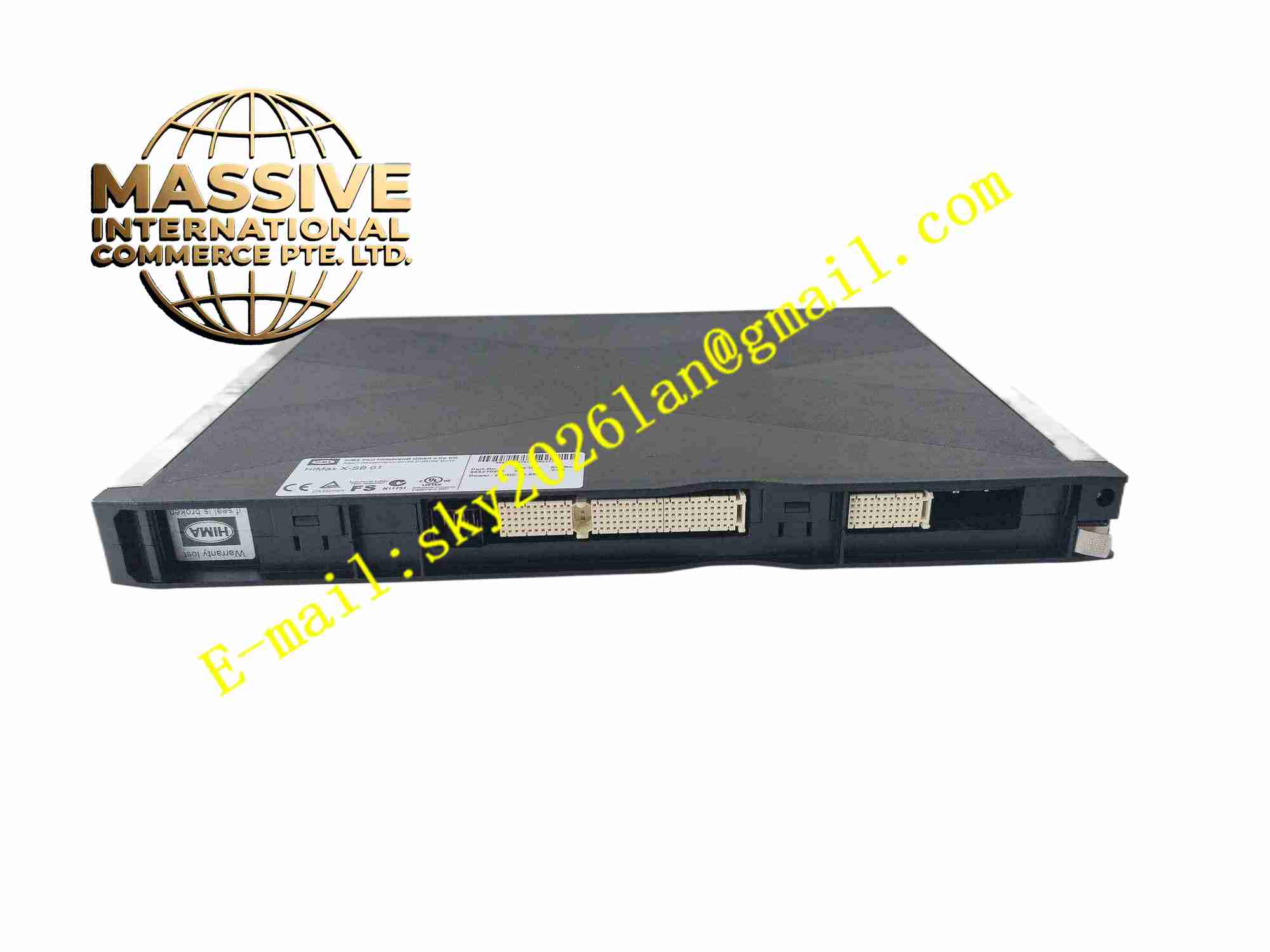
HIMA X-SB01 985210207
Technical Specifications: Rated supply voltage: 24VDC Power consumption: less than 200mA Number of channels: 16 digital input channels Safety certification: SIL3 IEC61508 Hazardous area certification: ATEX, IECEx, FM for Zone1/21, Division1 Isolation voltage: 2500VAC between system side and field side Communication interface: HIMax internal safety bus Mounting method: DIN rail 35mm mounting Protection class: IP20 Operating temperature: -20℃ to +60℃ Humidity range: 5%~95% non-condensing Response time: less than 20ms
Functional Features: Intrinsic safety energy limitation to protect field instruments in explosive hazardous zone. Continuous wire fault diagnosis for wire break and short circuit on each field channel. Galvanic isolation between safety system backplane and field hazardous loop. Hot swap capability, module replacement without full system shutdown. Transmit field safety digital signal to HIMax safety CPU via internal safety bus. Onboard self-test during system running. Fault status upload to safety controller and trigger safety alarm.
Application Scenarios: Oil and gas emergency shutdown system, chemical plant safety instrumented system, offshore platform safety control, fire and gas detection system, refinery safety interlock, power plant boiler protection system.
Performance Parameters: Diagnostic coverage higher than 99%. Mean time to dangerous failure meets SIL3 requirement. Relay and circuit service life for continuous long-term operation.
Material Composition: FR4 high temperature resistant high reliability circuit board. Intrinsic safety limiting resistors and Zener barrier components. Optocoupler isolation chips. Flame retardant plastic housing. Gold plated backplane connector and screw terminal block.
Structural Features: DIN rail pluggable module form factor. Front panel with LED status indicators for each channel. Screw terminal block for field hazardous area wiring. Backplane connector for HIMax safety bus connection. EMC shielding structure to resist industrial electromagnetic interference.
Working Principle: 24VDC power from HIMax backplane supplies the module circuit. Field digital signal from hazardous area safety sensors enters through screw terminals. Intrinsic safety barrier circuit limits voltage and current energy transmitted to field side to prevent explosion risk. Optocoupler provides galvanic isolation. Onboard diagnostic circuit monitors line impedance to detect wire break or short circuit. Valid signal and fault flags are transmitted to HIMax safety CPU via internal safety bus.
Installation Requirements: Mount on standard 35mm DIN rail inside safety control cabinet. Field wiring must use twisted shielded intrinsically safe cable. Separate intrinsically safe cables and non-safe power cables into different cable trays. Shield ground at single end. Tighten screw terminals to specified torque value. Ambient cabinet temperature maintained between -20℃ and +60℃.
Usage Notes: Only use original HIMA certified spare modules for replacement. Do not exceed intrinsic safety parameter limits on field terminals. Verify safety logic after module replacement. Carry out periodic function test following safety operation manual. Do not use the module outside certified hazardous area range.