



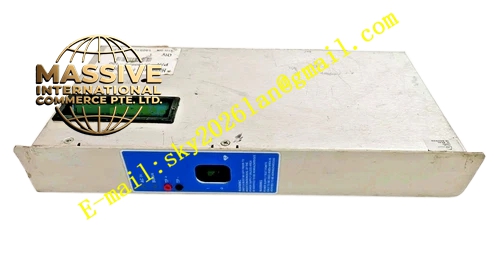
Description
Honeywell 51198685-100
Technical Specifications
- Channel count: 16 analog input channels
- Supported signals: 4–20 mA current loop
- Loop power supply: 24 V DC, 20 mA per channel
- Isolation: 500 VAC between field side and I/O card side
- Filter: RC low-pass filter, 10 Hz cutoff
- Backplane interface: Plugs directly to TPS analog input card front port
- Operating temperature: 0 °C to +60 °C
Functional Features Integrated 24 V DC loop power supply, eliminates external transmitter power supplies. Per-channel RC RFI filter, suppresses electromagnetic noise on current loop signals. Voltage clamping protection, limits overvoltage reaching the I/O card. Detachable field terminal block, field wiring modifications without disturbing I/O card connections. Channel labeling silk-screened for fast wiring identification. Loop current test point per channel, enables multimeter measurement without disconnecting wires.
Application Scenarios 4–20 mA transmitter signal termination for TPS analog input loops Field wiring interface replacement for legacy analog FTA units RFI filtering retrofits for strong-interference plant field loops Maintenance upgrades for analog I/O cabinet wiring
Performance Parameters
- Measurement accuracy: ±0.1% full scale
- Filter attenuation: 40 dB at 50 Hz noise frequency
- Loop current limit: 25 mA per channel
- Insulation resistance: ≥1000 MΩ
- Test point voltage: 1 V per mA loop current
Material Composition FR4 low-noise PCB substrate Precision metal film filter resistors Film filter capacitors TVS clamping diodes Detachable screw terminal block Metal mounting bracket
Structural Features Long rectangular PCB form factor. Front detachable terminal block arranges 16 channel wiring points. Rear gold-pin connector plugs directly to the analog input card. Test points aligned with each channel for multimeter access. Mounting bracket locks to I/O rack uprights.
Working Principle Field 4–20 mA transmitter signals connect to FTA terminals. The FTA supplies 24 V DC loop power to the transmitter through the wiring path. Return loop current passes through the RC RFI filter network, removing high-frequency noise before the signal reaches the I/O card. Voltage clamping diodes limit overvoltage spikes to a safe level for the analog input circuit. Test points provide a scaled voltage signal proportional to loop current, for quick field measurement. Processed signals route through the rear connector to the TPS analog input card for ADC conversion.
Installation Requirements Align the FTA rear connector with the analog I/O card front port, press fully seated. Wire transmitters to corresponding channel terminals, observe loop polarity. Configure 4–20 mA range in the TPS system configuration software. Measure loop current at test points during commissioning, confirm 4 mA at zero process value.
Usage Notes Loop wiring must observe correct polarity; reversed wiring causes zero output. Never short-circuit field loop terminals, short circuit triggers FTA overcurrent protection. Dust buildup on terminal blocks increases contact resistance; clean terminals annually. Do not install 24 V AC power on current loop terminals, this destroys the FTA loop supply circuit.







