



Description
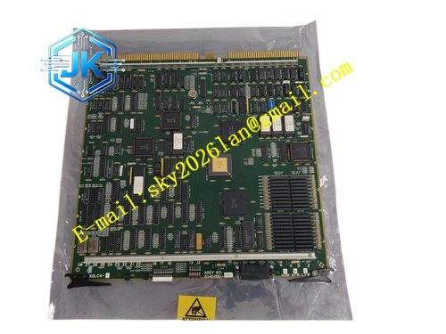
Honeywell 51401551-800
Technical Specifications Input Power: 24V DC Output Rails: 5V DC main logic rail, 12V DC auxiliary rail, -12V DC auxiliary rail Maximum Output Current: 18A for 5V rail, 4A for 12V rail, 1A for -12V rail Power Consumption: 5.8W Operating Temperature Range: 0℃ to 65℃ Storage Temperature Range: -40℃ to 85℃ Isolation Withstand Voltage: 1500V AC Relative Humidity: 5% to 95%, non-condensing
Functional Features It integrates multi-stage LC filter network to suppress power supply ripple and voltage spike noise. It implements over-voltage, under-voltage and over-current protection for each independent output rail. It supports power rail fault latching and fault status retention. It supports hot swap operation in redundant HPM rack configuration. It stores power alarm threshold parameters in non-volatile memory. It uploads real-time voltage, current data and power fault events to HPM diagnostic system. It provides power good signal for all HPM functional modules.
Application Scenarios Power distribution and stabilization for high-density HPM main control racks with heavy I/O load. Redundant power interface configuration for emergency shutdown and interlock control HPM controllers. Replacement and upgrade of old revision power regulator modules in legacy TPS HPM cabinets. Power condition monitoring for HPM racks installed in industrial areas with unstable grid voltage.
Performance Parameters 5V Output Ripple: ≤18mV peak to peak Voltage Monitoring Accuracy: ±0.04V Over-current Protection Response Time: ≤2ms Power Good Signal Delay: 100ms
Material Composition PCB Substrate: High-TG FR-4 multi-layer board with thick copper power plane layout High-current power MOSFET chips Precision voltage sampling and current sensing chips LC filtering inductor and capacitor components Gold-plated back edge fingers Cold-rolled steel front panel with electrostatic spray coating Large-area aluminum heat sink for power switching components
Structural Features Standard European pluggable card structure, installed in dedicated power regulator slot of HPM rack. Front panel is equipped with power run indicator light, rail fault indicator light and overload indicator light. Power input and distribution terminals are arranged on the side panel for 24V DC wiring. High-current power traces adopt widened copper foil layout to reduce temperature rise under full load. Power circuit and signal monitoring circuit are separated by isolation barrier.
Working Principle 24V DC input power enters the module through input terminals. The multi-stage filter circuit removes high-frequency noise and voltage spikes from input power. The synchronous buck regulation circuit converts raw 24V power into stable 5V, 12V and -12V output rails for all HPM internal modules. The sampling circuit continuously measures voltage and current value of each rail. When the value exceeds preset threshold, the protection circuit cuts off the corresponding output rail and triggers fault alarm. It transmits power status data and fault time stamp to HPM main processor through backplane bus.
Installation Requirements Insert the module vertically into the dedicated power regulator slot of HPM rack and tighten fixing screws. Connect 24V DC power cables to the input terminals according to polarity marking. Use adequate gauge power cables to avoid excessive voltage drop under full load. Download power alarm threshold parameters from Control Builder software after power on. Check rail voltage and current reading on the HPM power diagnostic page.
Precautions Release static electricity before plugging the module to protect sampling and power switching chips. Reverse polarity of 24V input causes immediate damage to internal power circuit. Do not modify the over-voltage and over-current threshold parameters without engineering authorization. Regularly clean rack air filter to maintain effective heat dissipation of power components. Redundant HPM racks must keep both power regulator modules working normally for bumpless switchover.







