



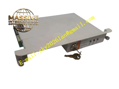
Description
Honeywell 620-0086
Technical Specifications
- Channel Quantity: 8 sinking solid-state output channels
- Output Type: 24 VDC sinking, NPN transistor
- Rated Output Current: 0.5 A per channel
- Channel Isolation: 500 VAC optical isolation between backplane and output side
- Backplane Interface: IPC620 I/O Link backplane bus
- Operating Temperature: 0 °C to +60 °C
- Power Consumption: 4.1 W maximum
- Hot Swap Support: Yes
Functional Features Solid-state switching with no mechanical wear and unlimited cycle life for low-power loads. Per-channel electronic current limiting and short-circuit protection. Automatic fault latch for overcurrent events, reset available through software command. Front panel LED indicator for each channel shows output on state. All output command frames carry CRC checksum for transmission verification.
Application Scenarios 24 VDC indicator lamp and status beacon control Proximity sensor and small field transmitter power switching Solid-state relay coil drive for low frequency interlock signals Fast pulse discrete output for low-speed counting trigger signals Spare solid-state output channel replacement for IPC620 racks
Performance Parameters
- Switching response time: Less than 20 μs
- Overcurrent protection trigger threshold: 0.6 A per channel
- Isolation withstand voltage: 500 VAC for 60 seconds
- Fault latch reset time: Less than 100 ms after reset command
Material Composition Multilayer FR4 PCB, power NPN transistor array, optocoupler isolators, current sensing resistors, TVS surge suppression diodes, decoupling capacitors, gold-plated backplane edge connector, UL94 V0 flame retardant plastic front panel.
Structural Features Standard eurocard plug-in dimension compatible with IPC620 rack. Front panel carries one LED indicator for each output channel. Internal isolation barrier separates backplane logic circuit and 24 VDC output load circuit. Anti-keying notch prevents reversed insertion into analog input slots. Power transistor layout reserves copper heat spreader area for thermal dissipation.
Working Principle CPU transmits output state command through I/O Link backplane bus. Onboard logic chip receives command and drives optocoupler to activate the corresponding NPN sinking transistor. The transistor pulls the field load circuit to ground to energize the load. Current sensing resistor monitors output channel current continuously. When current exceeds threshold, hardware current limiting activates and fault latch flag is set and sent to CPU.
Installation Requirements Total combined load current must not exceed module overall power rating. Use fuse protection at field load distribution terminal for each output group. Separate solid-state output wiring from analog instrument signal cables. Test channel on/off action and short-circuit protection response during commissioning.
Usage Notes This module cannot directly drive high-current loads exceeding 0.5 A per channel. Inductive 24 VDC loads require flyback diode installed across load terminals. Solid-state outputs have leakage current in off state which can illuminate high-sensitivity LED loads faintly. Do not apply voltage higher than 30 VDC to output terminals.







