



Description
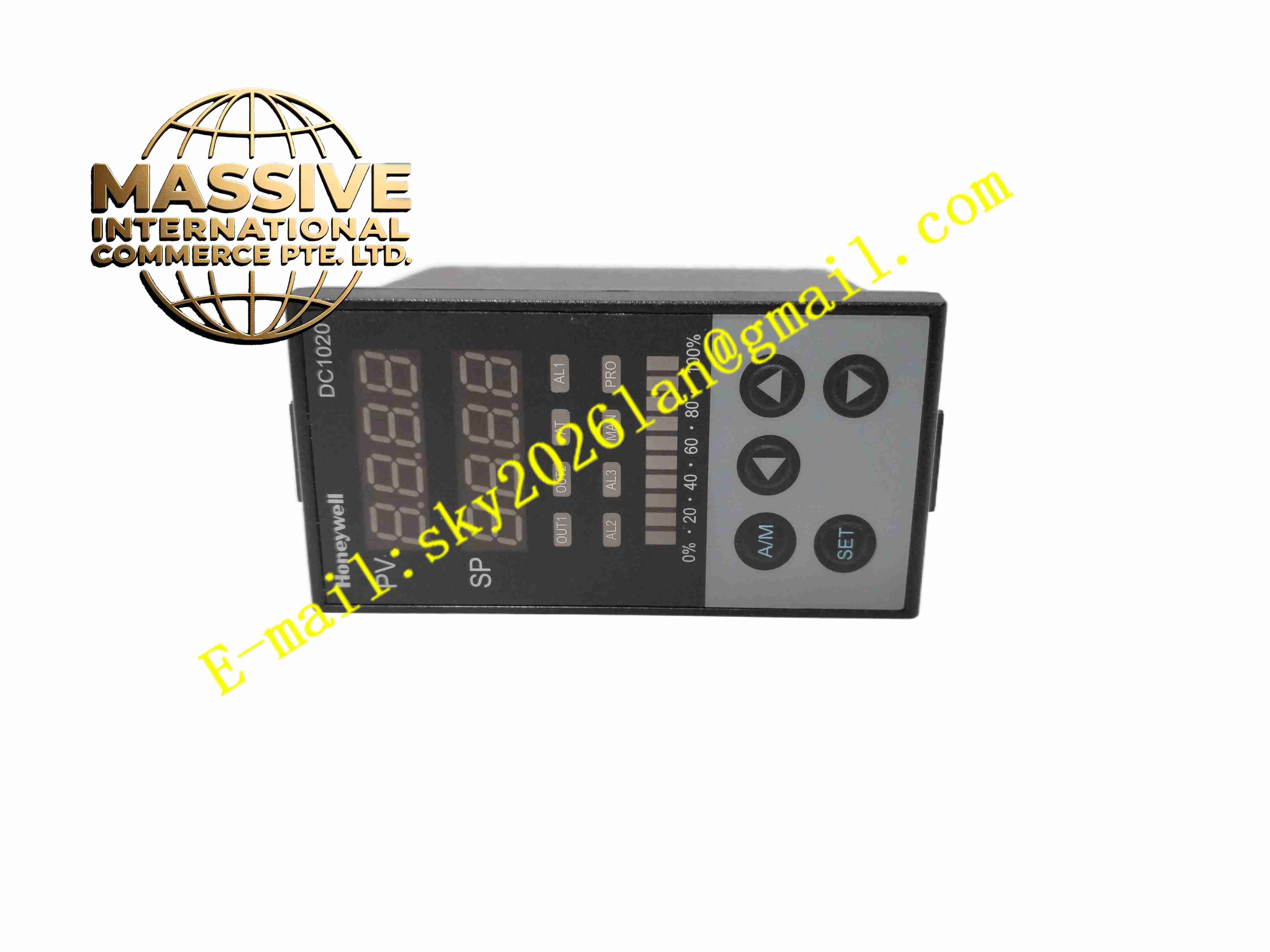
Honeywell DC1020CL
Technical Specifications Panel dimension 48 mm × 96 mm; power supply supports 90–265 VAC 50/60 Hz maximum 8 VA, or 15–50 VDC maximum 10 VA; universal input compatible with RTD, thermocouple, DC mA and DC voltage signals; measurement accuracy reaches ±0.5% of full span; sampling cycle 250 ms for process value; dual 4-digit 7-segment LED display for PV and SP; 10-segment bar graph for output percentage; communication interface supports RS232 or RS485 with Modbus RTU and ASCII protocols; operating ambient temperature -20 °C to +65 °C, non-condensing humidity 50% to 85%.
Functional Features Supports PID, ON/OFF and heat-cool dual-PID control algorithms; includes motor position control, phase angle and zero-crossing trigger modes; built-in auto-tuning function for PID parameters; configurable alarm thresholds for high, low and deviation alarms; remote setpoint input function; power failure resume selection between warm start and cold start; two independent programmable control outputs; front-panel A/M switch for automatic or manual operation.
Application Scenarios Plastic extrusion and injection molding machines, heat treatment furnaces, environmental test chambers, coating and drying ovens, packaging machinery, boiler auxiliary temperature control, semiconductor thermal testing equipment.
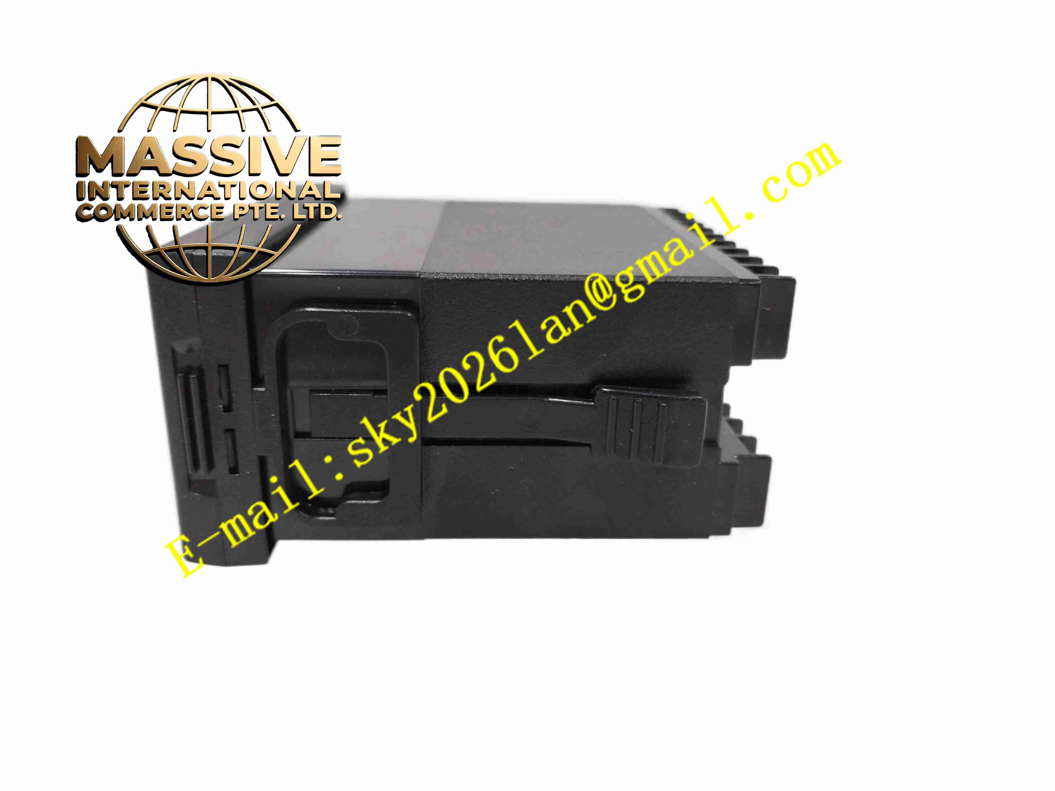
Material Composition Black flame-retardant ABS plastic front panel; polycarbonate transparent display window; FR4 printed circuit board with surface-mount electronic components; metal rear mounting clips; copper alloy screw terminals for sensor and output wiring.
Structural Characteristics Panel cutout mounting design; front panel integrates display window, function keys and status LEDs; rear wiring terminal block for sensor, power and output connections; metal clip locking mechanism secures the unit inside control cabinet cutouts.
Working Principle The controller reads analogue signals from field temperature sensors and converts raw signals into engineering values. The microprocessor compares measured process value against user-defined setpoint, calculates output value via selected control algorithm and drives the output hardware. Alarm circuits trigger indicator states once process variables cross configured threshold values.
Installation Requirements Prepare 48 mm × 96 mm panel cutout; insert the controller from front of the cabinet and fasten rear mounting clips; route sensor wiring separately from high-power AC cables; apply correct signal type configuration after power-on; complete PID auto-tuning after sensor installation.
Operation Notes Confirm sensor wiring polarity before energising the unit; avoid installation in locations with direct liquid splash or heavy conductive dust; calibrate input span after sensor replacement; disable control outputs before modifying wiring.







