



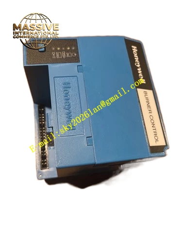
Description
Honeywell EC7850A1080
Technical Specifications
- Compatible detectors: C7027, C7035 UV flame detectors
- Supply voltage: 120 V AC 50/60 Hz
- Pre-purge time: 1 to 120 seconds adjustable
- Ignition trial time: 1 to 10 seconds adjustable
- Output ratings: Ignition transformer, fuel valve, blower motor interlock contacts, 5 A / 250 V AC
- Operating temperature: 0 °C to +60 °C
- Mounting: DIN rail or screw mount
Functional Features Automatic burner sequence: pre-purge, ignition trial, flame confirmation, normal run. Lockout on flame failure, requires manual reset after safety shutdown. Flame signal strength amplification and processing for connected UV detectors. On-board fault code display, indicates lockout reason for maintenance. Post-purge function after burner shutdown. Interlocks for air flow switch and high limit thermostat.
Application Scenarios Commercial gas boiler burner management Industrial process heater automatic burner control Package burner safety system integration Spare part replacement for failed older burner control relays
Performance Parameters
- Flame response time: ≤0.8 seconds
- Safety lockout accuracy: Meets NFPA 85 requirements
- Contact rating: 5 A / 250 V AC
- Ignition transformer output: 120 V AC primary
- Insulation resistance: ≥100 MΩ
Material Composition Flame retardant ABS housing Aluminum heat sink for power circuits Electromechanical relay outputs Screw terminal blocks PCB status LED indicator array Steel mounting bracket
Structural Features Rectangular plastic enclosure. Front LED array displays sequence state and fault codes. Rear screw terminals grouped by supply, detector, fuel valve and blower outputs. Mounting feet secure to cabinet back panel. Integral reset button on the front cover.
Working Principle On a call for heat, the control energizes the blower motor for the set pre-purge interval, sweeping combustion chamber air clear of unburned gas. After purge, the ignition transformer energizes, and the main fuel valve opens for the trial for ignition period. The connected UV flame detector sends a flame present signal to the control; if flame is confirmed within the trial window, ignition transformer de-energizes and the burner enters normal run. If no flame signal appears, the control immediately closes fuel valves, locks out and displays the fault code. On flameout during run, the control triggers immediate fuel shutdown and lockout.
Installation Requirements Mount the control in the burner cabinet, away from high-voltage ignition wiring. Connect flame detector, fuel valve, blower motor and ignition transformer wiring per the sequence diagram. Set pre-purge time and ignition trial time per burner manufacturer instructions. Press the reset button after power-up to initiate the burner sequence. Verify flame detector signal strength in the diagnostic menu.
Usage Notes Never bypass flame signal verification during commissioning, this creates explosion hazard. Lockout state requires manual reset; automatic reset is disabled for safety. Flame detector wiring must be routed separately from ignition high-voltage cables. Annual combustion safety inspection includes verifying pre-purge and trial time settings.







