



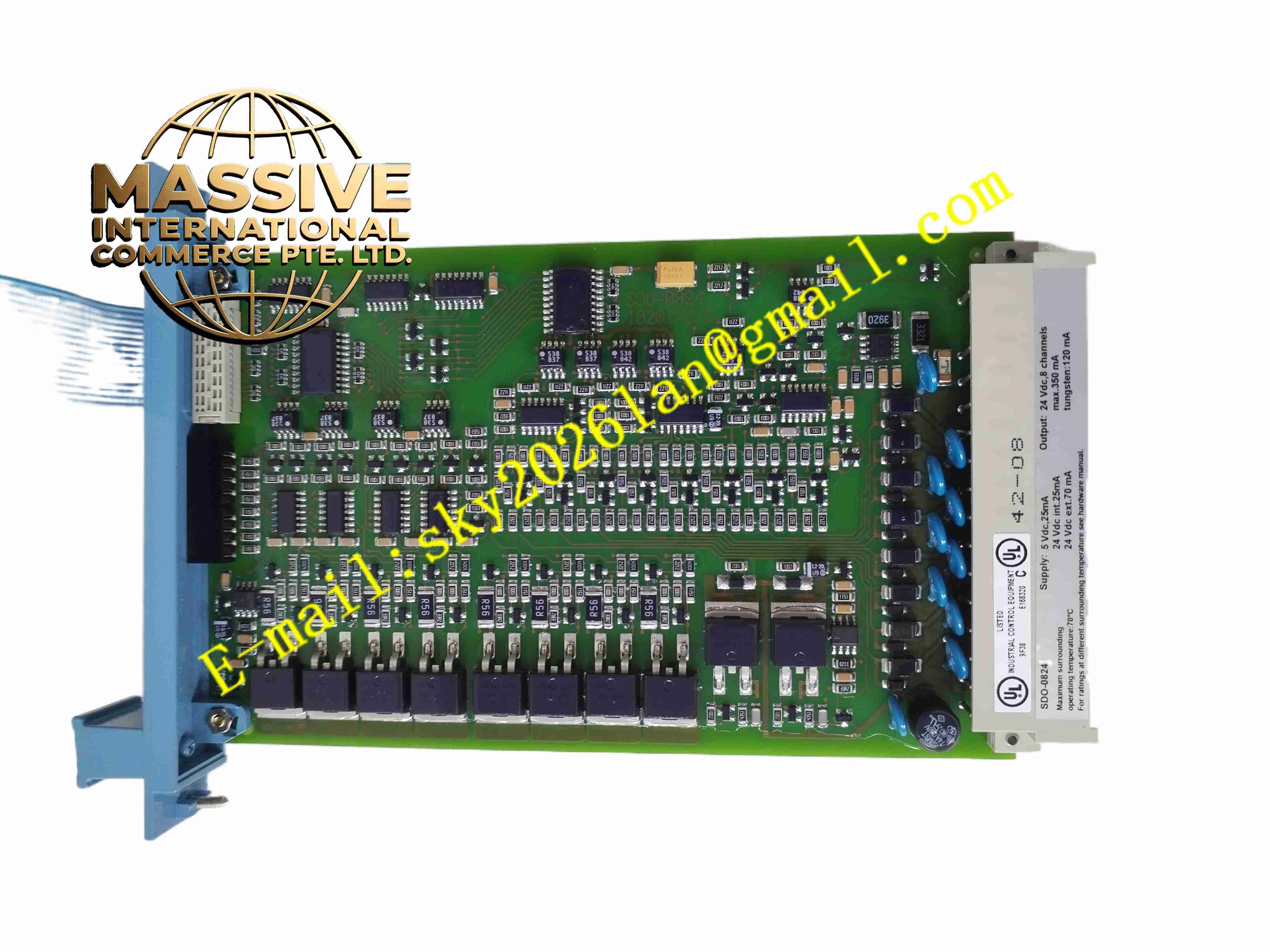
Description
Honeywell FC-SDO-0824 V1.3
Technical Specifications
- Product Type: Safety digital output module, hardware version V1.3
- Channel Count: 8 safety digital output channels
- Output Signal: 24VDC current output for safety actuators
- Safety Certification: IEC 61508 SIL2 / SIL3 applicable
- Bus Interface: Safety Manager rack backplane bus
- Diagnostic Functions: Output circuit monitoring, wire break detection, short circuit detection, feedback diagnosis
- Protection Rating: IP20
- Operating Temperature: -10 °C to +60 °C
- Mounting Method: Rack slot hot swappable module
- Cooling Method: Passive convection cooling
Functional Features
- 8 independent 24VDC safety output channels drive solenoid valves and safety relays.
- Per-channel feedback diagnosis monitors actual output circuit status continuously.
- Dual redundant output control path ensures safety de-energize to trip function.
- Hot swap function supports module replacement without full rack shutdown in redundant rack configuration.
- LED indicators display module power, running status and channel fault alarm.
- Per-channel overcurrent, short circuit and overvoltage protection.
- All outputs switch to predefined safe state automatically upon module or system fault.
- Fault event data uploads to safety controller for alarm and event recording.
- Conformal coated PCB is available for harsh industrial cabinet environment.
- V1.3 hardware revision optimizes internal diagnostic circuit stability.
Application Scenarios
- Petrochemical plant ESD solenoid valve trip control
- Boiler burner management safety fuel valve interlock output
- Offshore platform safety instrumented system actuator drive
- Refinery HIPPS system safety valve solenoid control
- Chemical reactor safety interlock trip output
Material Composition
- Housing: Flame-retardant polycarbonate plastic modular casing
- Main PCB: FR4 high reliability printed circuit board with conformal coating
- Switching components: Safety certified power MOSFET chips
- Isolation components: Optocoupler isolation chips
- Backplane connector: Gold-plated copper edge contact pins
- Protection components: Current limiting resistors and surge suppression diodes
Structural Characteristics
- Standard vertical single-slot rack module for Safety Manager rack installation.
- Front panel equipped with LED indicators for module and channel diagnostic state.
- Rear gold-plated edge connector inserts into rack safety backplane bus.
- Each output channel has independent drive circuit and feedback monitoring circuit.
- Internal isolation barrier separates safety logic circuit and field actuator circuit.
- Passive cooling design without fan components.
Working Principle Safety CPU sends enable or trip command to FC-SDO-0824 V1.3 module via backplane bus. The module controls MOSFET power switch to supply or cut off 24VDC power to field safety actuators. Feedback circuit samples output current and voltage continuously. When wire break, short circuit or actuator fault occurs, the module captures abnormal signal and reports fault to safety CPU. When safety trip condition triggers, all relevant channels cut off power and enter safe de-energized state.
Installation Requirements
- Insert FC-SDO-0824 V1.3 module into designated slot of Safety Manager rack.
- Use shielded twisted pair cable for solenoid valve and relay wiring.
- Separate safety output cables from high power motor cables.
- Complete protective earth connection for rack and control cabinet.
- Match actuator load current within module rated output range.
- Perform channel trip test and fault simulation test after wiring completion.
- Verify backplane connector contact integrity before power energization.
Usage Notes
- Execute hot swap maintenance strictly according to Safety Manager operation manual.
- Do not connect actuator load exceeding rated current specification.
- Keep cabinet dry and free of corrosive gas and conductive dust.
- Execute periodic SIL proof test for all output channels.
- Disconnect field actuator wiring before high voltage insulation resistance test.
- Use anti-static protection when handling spare modules.
- Replace module immediately when permanent hardware fault occurs.







