



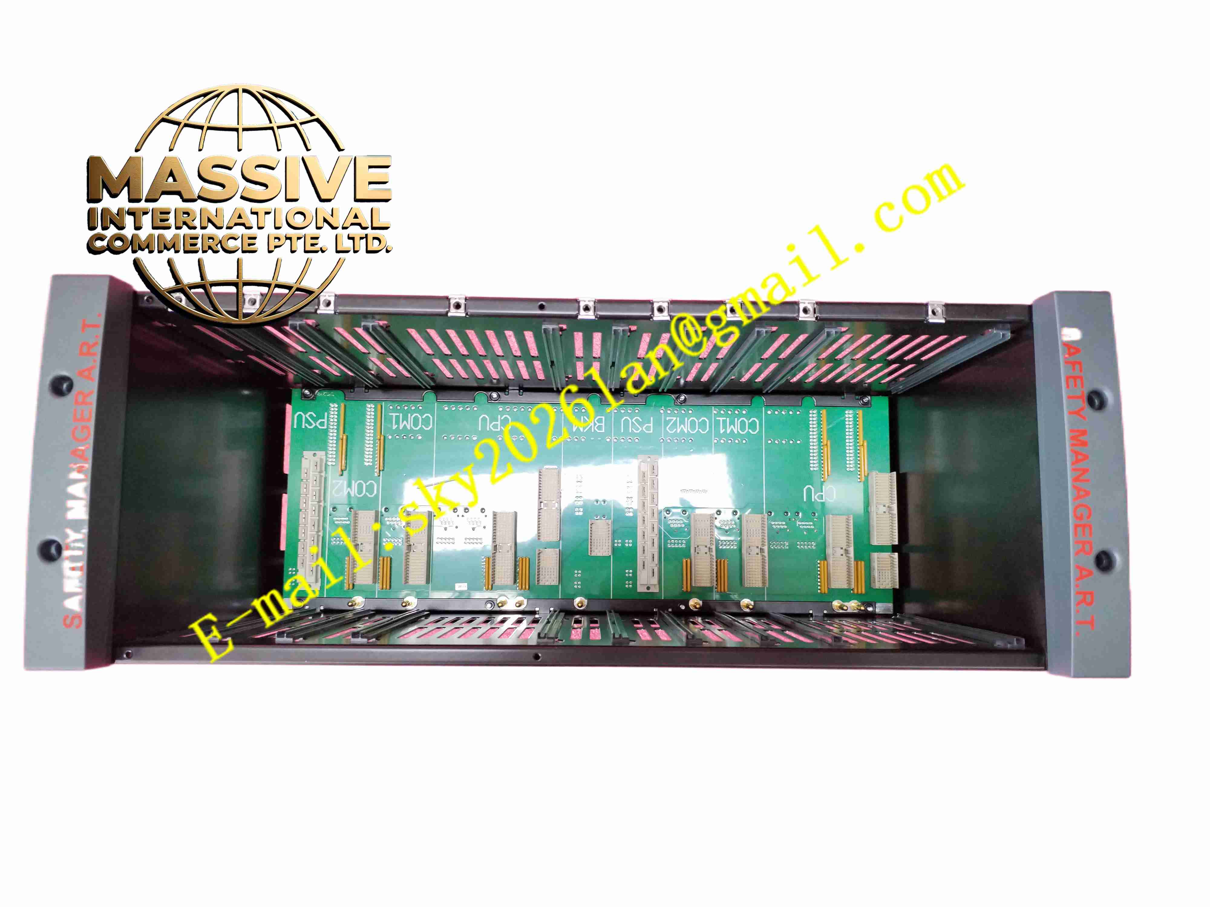
Description
Honeywell FS-CPCHAS-0002
Technical Specifications
- Product Type: Safety control processor rack chassis
- Slot Configuration: Dedicated slots for safety processor and redundant backup processor
- Backplane Interface: Safety Manager proprietary redundant backplane bus
- Power Interface: Matching power supply module connection terminals
- Protection Rating: IP20 for cabinet mounting
- Operating Temperature: -10 °C to +60 °C
- Storage Temperature: -20 °C to +70 °C
- Relative Humidity: 5 % to 95 %, non-condensing
- Mounting Method: Standard 19-inch rack mounting
- Material of Frame: Heavy-duty cold rolled steel frame
- Backplane PCB: FR4 high reliability printed circuit board with gold plated contacts
Functional Features
- Mechanical support and positioning for primary and redundant safety CPU modules.
- Redundant backplane bus realizes deterministic safety data transmission between processor and I/O racks.
- Integrated power distribution bus delivers regulated power to all modules inserted in the chassis.
- Gold plated edge connectors maintain stable electrical contact under vibration environment.
- Chassis ground bar provides unified protective earth connection for all rack modules.
- Slot keying mechanism prevents wrong module insertion into processor slots.
- Passive convection air flow channel supports natural cooling for hot-swap modules.
- Mechanical locking levers fix modules firmly and prevent loosening caused by vibration.
- Backplane continuous integrity monitoring detects connector contact failure.
- Compatible with Safety Manager series control processor spare modules.
Application Scenarios
- Petrochemical plant ESD safety logic solver main rack
- Refinery HIPPS safety instrumented system processor rack
- Offshore platform fire and gas safety controller cabinet
- Chemical reactor emergency shutdown system core rack
- Power plant boiler burner management safety control rack
Material Composition
- Main frame: Cold rolled steel with powder coating
- Backplane substrate: FR4 high Tg printed circuit board
- Connector pins: Gold plated copper alloy
- Slot locking components: Glass filled polycarbonate plastic
- Ground bus bar: Tin plated copper bar
- Mounting brackets: Powder coated steel
Structural Characteristics
- Standard 19-inch vertical rack mount metal frame structure.
- Rear integrated safety backplane PCB with multi-layer high speed signal traces.
- Front module slots with mechanical key pins for module type identification.
- Internal air flow channel designed for upward natural convection cooling.
- Integrated ground bus bar runs along the full length of chassis.
- Front retaining levers lock each module into corresponding slot.
Working Principle FS-CPCHAS-0002 provides mechanical carrier and electrical interconnection for safety processor modules. Rack power supply feeds DC power through chassis internal power bus to each slot. When primary processor runs, it communicates with I/O racks via backplane bus. In redundant configuration, primary and backup processor synchronize data through chassis backplane continuously. If primary processor fails, the chassis backplane supports bumpless switchover to backup processor without interrupting safety logic execution. Backplane contact monitoring circuit reports connection fault to processor.
Installation Requirements
- Install chassis into standard 19-inch industrial control cabinet.
- Fix mounting screws to specified torque to avoid frame deformation.
- Connect protective earth cable to chassis ground bus bar.
- Install matched rack power supply module to designated power slot.
- Insert control processor modules into keyed slots and lock front levers.
- Separate safety rack cable from high power AC cables in cable tray.
- Inspect all backplane connector pins for damage before power energization.
Usage Notes
- Do not insert non-Safety Manager modules into processor slots.
- Cut off rack power before removing backplane or chassis components.
- Keep cabinet air inlet clean and free of dust accumulation.
- Check ground connection tightness periodically under high vibration condition.
- Do not modify backplane wiring or trace routing.
- Handle chassis carefully to avoid bending backplane PCB.
- Replace chassis immediately when backplane traces or connector pins sustain permanent damage.







