



Description
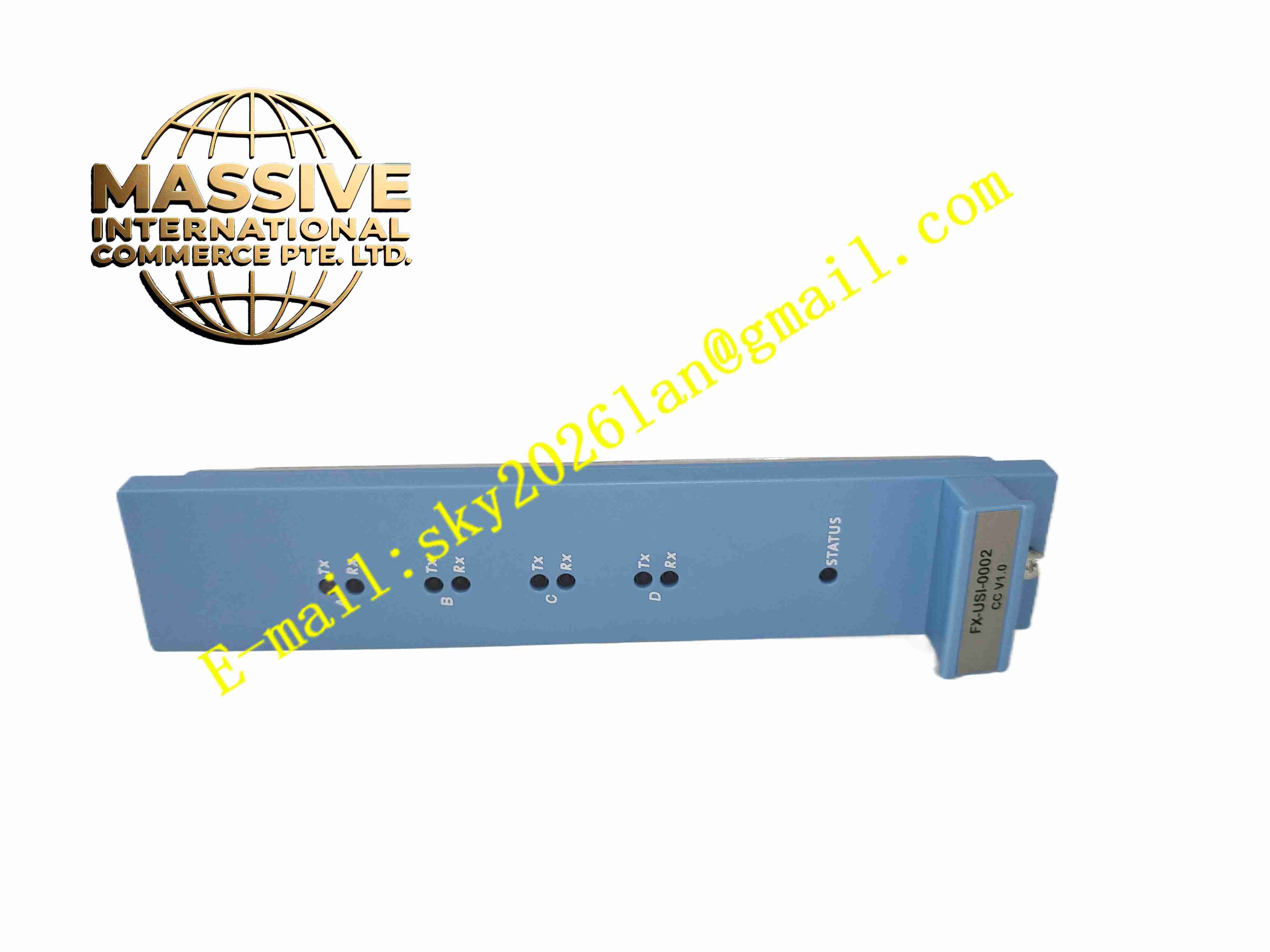
Honeywell FX-USI-0002
Technical Specifications:
- Power Supply: 5 VDC ±5%, max 1.2 A, supplied from rack backplane
- Processor: Motorola 8270 communication processor
- Memory: 8 MB Flash, 8 MB ECC SRAM, 256 KB shared RAM, EEPROM for MAC and configuration
- Communication Channels: 4 independent communication channels
- Interfaces: Dual fast Ethernet ports, dual RS232/RS485 serial ports
- Supported Protocols: EUCN proprietary safety bus, Modbus TCP, Modbus RTU, TCP/IP
- Galvanic Isolation: Field-to-system isolation, minimum 1.5 kVdc isolation rating
- Safety Certification: IEC 61508 SIL3, TÜV, UL, CE certified
- Operating Temperature: -5 °C to +70 °C
- Storage Temperature: -40 °C to +85 °C
- Relative Humidity: 10% to 95%, non-condensing
- Mounting: Hot swappable slot mount for Safety Manager rack
Function Features:
- Serve as deterministic communication coordinator for Safety Manager EUCN backplane bus
- Route mixed safety signals including 4–20 mA analog, discrete ESD switches and RTD/TC temperature signals
- Native HART pass-through for intelligent field device calibration and diagnostics without interrupting safety logic
- Continuous cross-channel self-diagnostics with high fault coverage to meet SIL3 requirements
- Galvanic isolation blocks cross-loop fault propagation across separate safety instrumented functions
- Support hot swap replacement and primary/backup redundant pairing for uninterrupted SIS operation
- Transmit safety alarm, diagnostic and event data to upper HMI and SCADA systems
- Front panel LED indicators for bus status, communication link and module fault
Application Scenarios:
- Oil and gas platform SIS safety instrumented systems
- Chemical plant emergency shutdown safety racks
- Refinery burner management and overpressure protection systems
- Power plant turbine and boiler safety protection systems
- LNG terminal safety control and HART field device integration
Material Composition:
- Main PCB: Multilayer FR4 fiberglass printed circuit board with conformal coating
- Core Components: Communication processor, ECC memory chips, isolated transceivers
- Connectors: Gold-plated edge connector for rack backplane
- Front Panel: Blue flame retardant plastic panel with LED indicator windows
- Passive Components: High precision resistors, capacitors and surge suppression diodes
- Locking Hardware: Reinforced plastic rack latches
Structural Features:
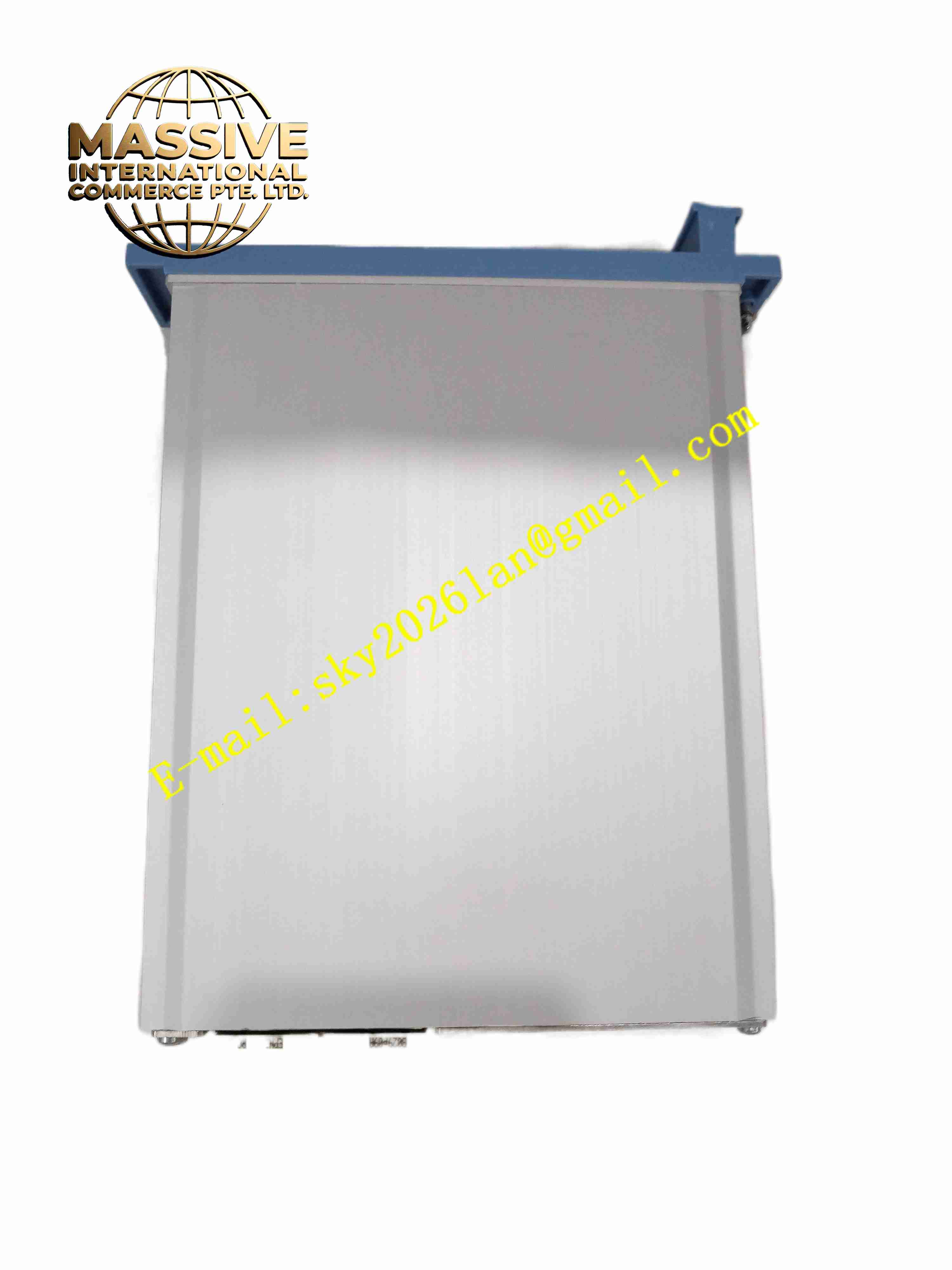
- Vertical plug-in Eurocard form factor for Honeywell Safety Manager rack chassis
- Blue front panel with dedicated LED indicators for bus and channel fault status
- Rear gold-plated edge connector for backplane 5 VDC power and EUCN safety bus
- PCB layout separates safety logic circuit and external communication interfaces
- Plastic locking latches for secure insertion and extraction
- Conformal coating protects PCB against dust, moisture and corrosive vapor
Working Principle: The module receives safety data from quad safety processors via EUCN backplane bus and exchanges data with distributed safety I/O termination assemblies. It performs protocol translation and signal isolation between safety bus and external Ethernet or serial communication links. HART signals pass transparently through the module to allow remote configuration of HART field transmitters. Onboard diagnostic circuits continuously monitor internal hardware and communication link health. When fault is detected, fault information reports to safety controller and front panel LED activates. Redundant USI modules monitor each other and perform bumpless switchover upon primary module failure.
Installation Requirements:
- Insert module into designated slot of Honeywell Safety Manager rack
- Wear anti-static wristband during module replacement
- Use shielded twisted pair cables for serial communication wiring
- Use shielded Ethernet cables for upper system network connection
- Verify backplane connector cleanliness before module insertion
- Complete rack protective earth connection
- Maintain cabinet ventilation and temperature control
Usage Notes:
- Load validated module configuration via Honeywell safety configuration software before commissioning
- Perform full system proof test after module replacement
- Backup configuration data to external storage media
- Do not modify safety firmware without Honeywell official approval
- Disconnect rack power before removing module unless hot swap operation is approved
- Inspect front panel LED indicators and fault logs for routine health check







