Description
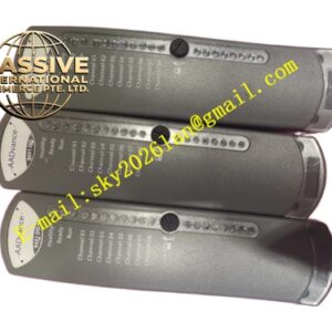
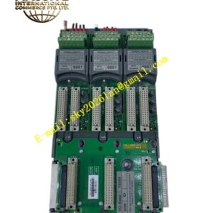
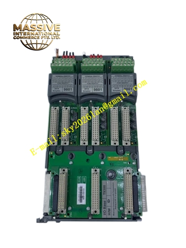
ICS Triplex 9300
Technical Specifications:
- Product Type: I/O base unit / passive backplane
- Module Capacity: Supports up to 3 I/O modules of any type (digital or analog)
- Power Supply: 24 VDC (20-32 VDC range)
- Communication Interface: AADvance backplane communication (IMB)
- Dimensions: 300 mm x 100 mm x 50 mm
- Weight: 0.8 kg
- Operating Temperature: -25°C to +70°C
- Protection Level: IP20
- Mounting: DIN rail or panel mounting
Functional Features:
- Passive backplane with no application firmware
- Supports up to three I/O modules per base unit
- Distributes system power and internal buses to connected modules
- Direct plug and socket connection to T9100 processor base unit (I/O Bus 1)
- Expansion capability via T9310 cable for additional rows (I/O Bus 2)
- Module positions numbered from 01 to 24 for unique identification
- Secured with top and bottom clips inserted into slots
- Compatible with all AADvance I/O module types
- SIL 3 approved for certified safety architectures
Application Scenarios:
- I/O expansion in safety instrumented systems
- Chemical processing plant control systems
- Oil and gas production monitoring
- Power generation equipment protection
- Industrial automation requiring scalable I/O
Performance Parameters:
- Operating temperature range from -25°C to +70°C
- Compatible with IEC 61508 SIL 3 architectures
- Reliable power distribution to all connected modules
- Stable backplane communication under industrial conditions
- High availability through modular design
Material Composition:
- Industrial-grade metal housing
- High-quality backplane PCB
- Durable connector sockets
- Corrosion-resistant finish
Structural Characteristics:
- Compact three-module capacity design
- Leftmost position designated as slot 01
- Unique module identification via bus and slot numbers (e.g., 1-01)
- Direct plug connection to adjacent base units
- T9310 expansion cable compatibility for multi-row installations
Working Principle: The passive backplane distributes 24 VDC system power to installed I/O modules and provides the communication pathways for command and response buses. Each module position is electrically connected to the internal bus structure, enabling seamless data exchange between I/O modules and the processor base unit. The base unit contains no active electronics, ensuring high reliability.
Installation Requirements:
- Mount on DIN rail or panel using retaining clips
- Connect to T9100 processor base unit on right-hand side for Bus 1
- Use T9310 expansion cable for left-hand side connections (Bus 2)
- Secure base units with top and bottom clips
- Install end stops on DIN rails at assembly ends
- Ensure proper grounding per system requirements
Usage Precautions:
- Verify module compatibility before insertion
- Ensure clips are fully engaged for secure mounting
- Do not force modules into sockets
- Monitor LED indicators on connected modules for status
- Maintain clean environment to prevent contamination
- Follow proper ESD procedures during module handling