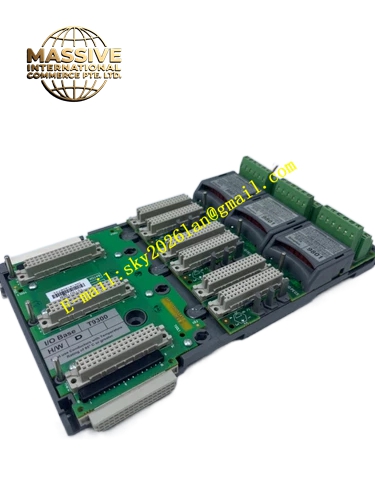
Description
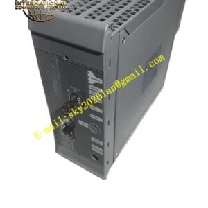
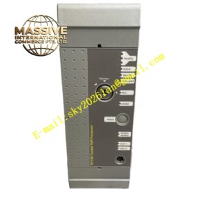
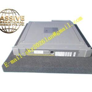
ICS Triplex T3404
Technical Specifications
| Parameter | Specification |
|---|---|
| Manufacturer | ICS Triplex (Rockwell Automation) |
| Product Series | Regent System |
| Module Type | AC Digital Input Module |
| Input Channels | 16 independent discrete input channels |
| Nominal Input Voltage | 110 VAC |
| Input Voltage Range | Compatible with standard 110 VAC industrial control signals |
| Signal Isolation | Opto-galvanic isolation between field and logic |
| Chassis Compatibility | T3300 Regent I/O Chassis |
| Dimensions | 3.3 cm × 26.5 cm × 35.7 cm |
| Weight | 1.26 kg |
| Operating Temperature | -25°C to +60°C |
Functional Features
- 16 AC Input Channels: High-density 110 VAC input capacity for large-scale switch monitoring
- High-Voltage Field Interface: Direct interfacing with 110 VAC control circuits eliminates the need for external interposing relays
- Comprehensive Galvanic Isolation: Isolation barriers protect the controller from high-voltage field transients
- Standard Chassis Integration: Mounts directly into the T3300 Regent I/O chassis
- Robust Environmental Design: Operates reliably from -25°C to +60°C
- Front-Panel Status Indication: LED indicators display channel states and module health
Application Scenarios
- Power generation plant switchgear monitoring
- High-voltage motor control center feedback
- 110 VAC control circuit interfaces in heavy industry
- Transformer and substation status monitoring
- Large compressor and pump starter feedback
- Conveyor system limit switch interfaces at 110 VAC
- Legacy system upgrades maintaining 110 VAC I/O standards
Performance Parameters
- Input Voltage Rating: 110 VAC nominal, suitable for standard industrial control voltages
- Isolation Strength: High-voltage withstand capability between field and logic circuits
- Channel Density: 16 channels per module provides efficient cabinet space utilization
- Response Time: Fast AC signal detection with zero-crossing or direct detection circuitry
- Power Consumption: Efficient operation with minimal heat generation
Material Composition
- Enclosure: Industrial-grade metal housing with protective finish
- Circuit Board: Multilayer PCB with AC input conditioning and isolation circuits
- Optocouplers: High-voltage rated optocouplers for AC line isolation
- Input Protection: Metal oxide varistors and transient suppression components
- Connectors: High-reliability terminal blocks for AC field wiring
Structural Characteristics
- Standard Regent Module Profile: 3.3 cm × 26.5 cm × 35.7 cm form factor for T3300 chassis
- Front-Panel Terminals: High-voltage rated screw terminals for secure AC wiring
- Channel Status LEDs: Individual LED indicators for each of the 16 input channels
- Backplane Connector: Direct plug-in interface to the Regent chassis backplane
- High-Voltage Clearance: Adequate creepage and clearance distances for 110 VAC operation
Working Principle
The T3404 module receives 110 VAC signals from field switches and contacts. Each channel includes an AC input conditioning circuit that rectifies and filters the AC signal before applying it to a high-voltage optocoupler. The optocoupler provides complete galvanic isolation between the 110 VAC field circuit and the low-voltage logic circuit. The isolated DC signal is then processed by onboard logic to determine the input state, which is communicated to the Regent controller via the chassis backplane during each I/O scan cycle.
Installation Requirements
- Install in a compatible T3300 Regent I/O chassis slot
- Use appropriately rated wire for 110 VAC field connections
- Ensure proper grounding of the chassis and cable shields
- Verify that field devices provide compatible 110 VAC output signals
- Maintain adequate clearance from other low-voltage signal cables
- Follow local electrical codes for 110 VAC wiring practices
Operating Precautions
- Verify input voltage remains within acceptable AC voltage ranges
- Exercise caution when servicing 110 VAC field wiring
- Monitor channel status LEDs for fault indication
- Do not mix 110 VAC and low-voltage signals in the same cable bundle
- Ensure proper torque on terminal screws to prevent overheating
- Replace modules only with power removed from field circuits
- Follow lockout/tagout procedures when maintaining 110 VAC connections