Description
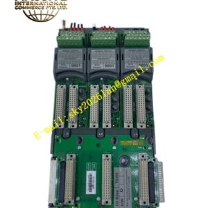
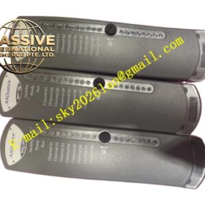
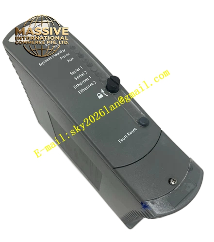
ICS Triplex‑T8312 Expander Interface Adapter
Technical Specifications:
- Operating Power Input: 24 VDC ±10 %, built‑in reverse polarity protection circuit
- Typical Operating Current: 85 mA under 24 VDC operating voltage
- Backplane Communication Baud Rate: 1.5 Mbps dedicated industrial safety bus rate
- Dielectric Isolation Rating: 500 VDC isolation potential between main chassis and expander chassis circuits
- Operational Ambient Temperature: 0 °C to +60 °C
- Storage Ambient Temperature: −40 °C to +85 °C
- Relative Humidity Range: 5 %‑95 %, non‑condensing environmental condition
- Operational Vibration Resistance: 2 g acceleration, 10 Hz‑500 Hz frequency spectrum
- Mechanical Shock Resistance: 15 g peak acceleration, 11 ms shock duration
- Net Weight: 0.65 kg
- Safety Compliance Certifications: ATEX, IECEx, CE mark, SIL 3 functional safety certification for Trusted system architecture
Functional Features:
- Implements complete triple‑modular redundant TMR communication architecture, removes single‑point communication failure risk
- Equips integrated EMC metal shielding shell, restrains strong electromagnetic interference from on‑site industrial equipment
- Adopts locking‑type 12‑pin ODU connectors, prevents loose connection under continuous mechanical vibration
- Hardware DIP switch completes chassis ID configuration. No software modification needed for multi‑chassis layout setup
- Carries mechanical release button, supports quick disassembly without tool‑caused hardware damage
- Executes real‑time communication fault diagnosis, uploads link fault information to main processor unit
Application Scenarios: Large‑scale oil and gas processing plants, thermal power generation facilities, petrochemical complex units, chemical process safety interlock systems, offshore platform safety instrumented systems, all project sites requiring large‑volume distributed I/O resource expansion.
Material Composition:
- Outer protective housing: Die‑cast aluminum alloy with anti‑corrosion surface treatment coating
- Internal circuit substrate: Multi‑layer industrial PCB with conformal protective coating
- Connector components: Gold‑plated high‑reliability ODU contact terminals, 96‑pin type‑C backplane connectors
- Fastening hardware: Stainless steel anti‑vibration locking screws
Structural Characteristics: Standard 8U chassis‑mount module form factor, compatible with qualified hot‑swap operation. Dual 96‑pin backplane mating interfaces are arranged on the rear side. Multiple expander signal output connectors are placed on front panel. One‑piece metal shielding housing fully wraps internal circuit boards to block external electromagnetic noise. Clip‑on physical installation structure fits on the rear section of Trusted controller chassis.
Working Principle: Receives triplicated TMR data stream transmitted from main controller chassis backplane. Distributes synchronized triple‑channel control signals and diagnostic data to every connected expander chassis. Completes electrical signal isolation and noise filtering during signal transmission process. Transmits expander chassis running status and I/O feedback signals back to main rack. Carries out hardware‑level channel voting logic to detect communication channel faults.
Installation Requirements:
- Mount the module on the rear connector assembly of Trusted main controller chassis.
- Configure DIP‑switch chassis ID strictly. Main chassis fixed ID value is 1. Expander chassis ID setting range covers 2‑8.
- Reserve minimum 20 mm ventilation clearance around module surface for effective heat dissipation.
- Deploy only original matching ODU expander cables. Do not apply third‑party substitute cables.
- Connect chassis protective earth terminal to site safety grounding busbar reliably.
Usage Notes:
- Do not insert or extract the module under powered‑on status, unless the whole system is configured and approved for hot‑swap operation.
- Confirm chassis ID setting correctness before power supply input. Conflicting ID values will trigger complete system communication failure.
- Avoid installation locations close to high‑power frequency converters and high‑voltage contactor assemblies.
- Perform regular inspection of connector locking state for offshore sites and high‑vibration operating environments.