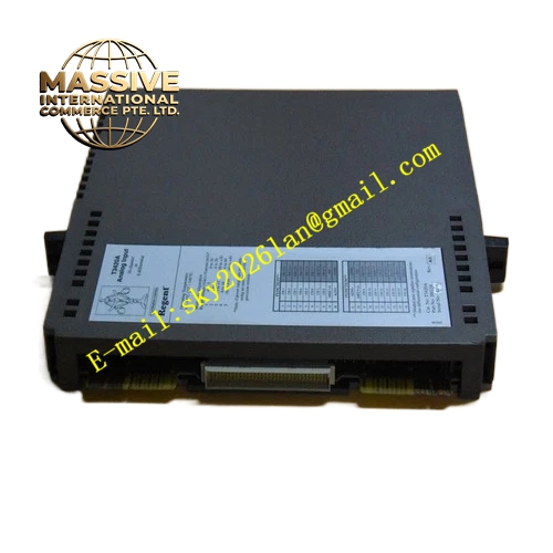
Description
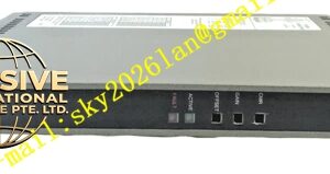
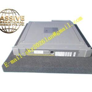
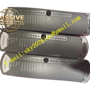
ICS Triplex T8314
Technical Specifications
| Parameter | Specification |
|---|---|
| Model Number | T8314 |
| Brand | ICS Triplex (Rockwell Automation) |
| Product Type | Trusted Expander Interface Module |
| Application | Chassis-to-Chassis IMB Extension |
| Power Consumption | 20 W (typical) |
| Weight | 2.34 kg |
| Dimensions | 30.0 × 14.5 × 4.5 cm |
| Operating Temperature | -5°C to +60°C |
| Storage Temperature | -25°C to 70°C |
| System Compatibility | Trusted TMR Controller Systems |
| Transmission Distance | Up to 10 km |
| Fiber Type | Single-mode fiber optic cable |
| Connectors | SC type connectors for Tx and Rx |
| Mounting | Standard Trusted chassis slot |
| Certifications | IEC 61508 SIL 3, CE, RoHS |
Functional Features
- Scalable Design: Links additional I/O chassis for seamless system expansion
- Secure Communication: Fast, error-checked data exchange ensures reliability as system complexity grows
- Long-Distance Fiber Optic Link: Extends the Expander Bus up to 10 km via single-mode fiber
- Diagnostic Capabilities: Real-time monitoring of connections and status for proactive maintenance
- Triple Redundant Path Monitoring: Aligns with TMR architecture for high-integrity communication
- Comprehensive Internal Self-Testing: Hardware failure detection through continuous diagnostics
- Hot-Swappable: Supports replacement without powering down the system
- Robust Mechanical Keying: Ensures correct insertion into the Trusted chassis
Application Scenarios
- Large-scale Safety Instrumented Systems (SIS) in oil and gas
- Complex Emergency Shutdown (ESD) systems requiring distributed I/O
- Fire & Gas (F&G) systems with remote sensor locations
- Petrochemical plants with widely separated process units
- Power generation facilities with distributed control rooms
Performance Parameters
- Data Throughput: High-speed data exchange between chassis
- Transmission Distance: Up to 10 km over single-mode fiber
- Error Detection: Robust error-checking ensures data integrity
- Response Time: Low-latency communication for real-time control
Material Composition
- Enclosure: Industrial-grade metal housing
- Circuit Board: Multilayer PCB with fiber optic transceiver circuits
- Fiber Connectors: SC-type industrial fiber optic connectors
- Components: Extended-temperature-range optoelectronic components
Structural Characteristics
- Standard Chassis Slot: Fits into Trusted TMR controller chassis
- Fiber Optic Ports: SC connectors for transmit and receive channels
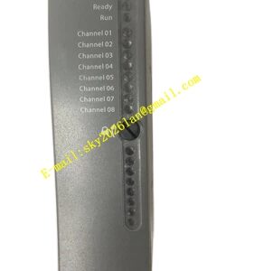
- Front-Panel Indicators: Status LEDs for link activity and diagnostics
- Compact Design: Space-efficient form factor for control cabinet installation
Working Principle
The T8314 module interfaces between the main Trusted chassis and remote expander chassis. It converts electrical backplane signals into optical signals for transmission over single-mode fiber. At the remote end, a corresponding T8314 converts the optical signals back to electrical signals for the expander chassis backplane. Triple redundant data paths ensure that communication integrity is maintained even if one path experiences a fault. Continuous diagnostic monitoring verifies link health and reports any communication errors.
Installation Requirements
- Install in designated Trusted rack slots at both main and remote chassis
- Use qualified single-mode fiber optic cable with SC connectors
- Ensure proper fiber handling to prevent damage or contamination
- Verify system power meets specifications before installation
- Maintain bend radius requirements for fiber optic cables
Operating Precautions
- Inspect fiber connectors regularly for cleanliness and damage
- Monitor link status LEDs for communication fault indication
- Avoid exceeding the maximum fiber bend radius
- Protect fiber cables from physical damage and crushing
- Maintain spare modules for rapid replacement of failed units