Description
ICS Triplex T8461C
Technical Specifications
| Parameter | Specification |
|---|---|
| Manufacturer | ICS Triplex (Rockwell Automation) |
| Model Number | T8461C |
| Product Series | Trusted TMR System (T8100/T8110 architectures) |
| Module Type | Digital Output (40 Channels) |
| Nominal Output Voltage | 24 VDC / 48 VDC |
| Output Channels | 40 channels, divided into 5 power groups (8 channels per group) |
| Continuous Output Current | 0.75 A per channel |
| Maximum Current Per Power Group | 6 A |
| Minimum Load Current | 25 mA |
| On-Resistance | 1.6 Ω |
| Output Off-State Resistance | 33 kΩ |
| Maximum Capacitance Pre-Release | 30–55 µF (Version 3.5), 3500 µF at 0.75 A |
| Weight | 1.3 kg |
| Dimensions | 266 mm (H) × 31 mm (W) × 303 mm (D) |
| Safety Rating | SIL 3 capable (in TMR configurations) |
| Operating Temperature | -40°C to +70°C |
| Storage Temperature | -25°C to +70°C |
| Humidity | 10%–95% (non-condensing) |
| Protection Rating | IP20 |
Functional Features
- Triple Modular Redundant Design: Three independent output slices cross-checked through hardware voting logic maximize system availability
- High Channel Density: 40 independent isolated digital output channels in a compact 3.1 cm wide form factor
- Comprehensive Line Monitoring: Detects open-circuit wiring and short-circuit faults on the field side
- Self-Testing Architecture: Automatic pulse-testing of output switches ensures they can transition to safety state even when energized for long periods
- Built-In Overcurrent Protection: Safeguards connected field devices from damage
- Sequence of Events Recording: 1 ms resolution timestamping of output state changes
- Hot-Swap Capability: Live module replacement without powering down the system
- Environmental Resilience: Engineered for extreme temperatures and corrosive atmospheres
Application Scenarios
- Emergency Shutdown (ESD) valve control
- Fire & Gas (F&G) alarm and suppression actuation
- Burner Management System (BMS) fuel valve control
- Safety interlock relay driving
- Motor starter coil energization
- Solenoid valve control in process safety systems
Performance Parameters
- Output Drive Capability: 0.75 A continuous per channel, 6 A per power group
- Switching Speed: Fast response to safety-critical commands
- Fault Detection: Real-time detection of open circuits, short circuits, and load faults
- Safety Integrity: SIL 3 performance maintained through TMR voting and diagnostics
- Capacitive Load Handling: Pre-release capacitance management up to 3500 µF
Material Composition
- Enclosure: Ruggedized industrial metal housing with corrosion-resistant finish
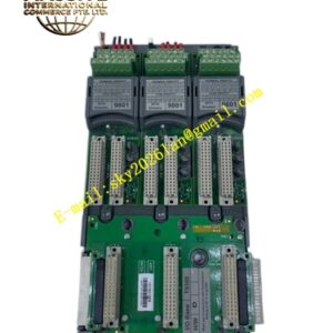
- Circuit Board: Multilayer PCB with high-current output driver circuits
- Output Devices: Industrial-grade solid-state switches with overcurrent protection
- Connectors: High-reliability backplane and field terminal assemblies
Structural Characteristics
- Slim Module Profile: 31 mm width maximizes I/O density in the chassis
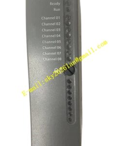
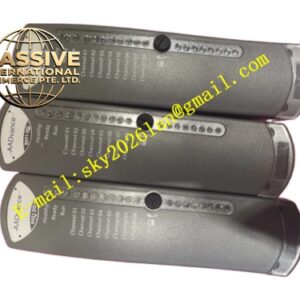
- Front-Panel LEDs: 40 channel indicators plus module status LEDs for power, fault, and active/standby modes
- Power Grouping: Five isolated power groups of eight channels each
- Backplane Interface: Trusted TMR backplane communication bus
Working Principle
The T8461C receives output commands from the Trusted processor via the TMR backplane. Three independent output circuits per channel receive the command simultaneously. Each circuit drives the field load through its own solid-state switch. The voter verifies that at least two of the three circuits agree before allowing current to flow to the field device. Line monitoring circuits continuously measure output voltage and current to detect wiring faults. Pulse-testing periodically verifies switch integrity without disturbing the output state.
Installation Requirements
- Install in a Trusted T8100/T8110 series chassis
- Connect field power within the 18–58 VDC range
- Ensure minimum load current of 25 mA per channel for proper monitoring
- Use appropriate cable sizing for 0.75 A per channel
- Configure companion slots or SmartSlots for hot-swap capability
Operating Precautions
- Verify output load currents remain within specified limits
- Monitor channel LEDs for fault indication
- Perform periodic proof testing of output switches
- Replace failed modules promptly to restore TMR redundancy
- Ensure field power supply capacity meets total load requirements
- Follow proper ESD procedures during module handling