Description
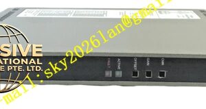
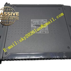
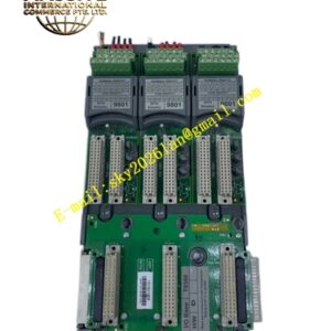
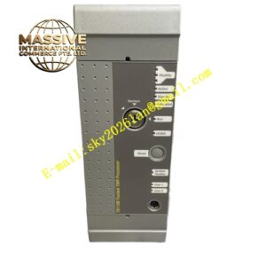
ICS Triplex T8830
Technical Specifications:
- Number of Channels: 40 analogue input channels
- Field Device Connection: Industry standard 2-wire connections
- Field Supply Voltage: 18 to 32 Vdc
- Maximum Current per Loop: 50 mA (fused per channel)
- Power Consumption: 0.25 W (including LED indicators)
- Operating Temperature: 0°C to +60°C (+32°F to +140°F)
- Non-Operating Temperature: -25°C to +70°C (-13°F to +158°F)
- Relative Humidity: 10% to 95%, non-condensing
- Mounting: Standard DIN rail compatibility
- Dimensions (HxWxD): 111 mm x 335 mm x 51 mm (4.4 in x 13.2 in x 2 in)
- Weight: 900 g (2 lb)
Functional Features:
- 40 input channels per assembly for high-density signal termination
- Industry standard 2-wire field device connections for simplified wiring
- SmartSlot connection enabling one-to-many hot replacement of input modules without system interruption
- Fused field power supply per channel for individual circuit protection
- On-board LED indication providing clear visual confirmation of field power supply integrity
- Standard DIN rail mounting for convenient installation and optimal space utilization
- 24 Vdc operation ensuring compatibility with standard industrial power sources
Application Scenarios:
- Process variable monitoring in oil and gas refineries
- Temperature and pressure transmitter signal termination in chemical plants
- Flow measurement system interfaces in pipeline operations
- Level monitoring in storage tank farms
- Analytical instrument connections in pharmaceutical manufacturing
- Safety instrumented system analogue input termination
Performance Parameters:
- Channel Density: 40 channels per assembly
- Signal Compatibility: Standard 4-20 mA and voltage signals
- Loop Power: 50 mA maximum per channel with individual fusing
- Hot Swap Capability: SmartSlot enables module replacement without process interruption
Material Composition:
- Housing: Industrial-grade metal enclosure with protective finish
- Terminal Blocks: High-quality screw terminals accepting up to 16 AWG conductors
- PCB: Conformal coated circuit board for moisture and contamination resistance
- Fuses: Replaceable per-channel fuses for field circuit protection
Structural Characteristics:
- Compact horizontal form factor for DIN rail mounting
- Three-section terminal layout for organized field wiring
- Front-facing LED indicators for power status monitoring
- SmartSlot connector interface for direct module mating
- Clear channel numbering and wire routing guides
Working Principle: The T8830 receives analogue signals from field-mounted instruments through dedicated 2-wire connections. Each channel incorporates individual fuse protection to isolate field faults. The signals pass through the termination assembly to the connected T8431 TMR Analogue Input Module via the SmartSlot interface. The LED indicators provide immediate visual feedback regarding the presence of field power on each channel group.
Installation Requirements:
- Mount on standard 35 mm DIN rail in industrial enclosures
- Connect field wiring using conductors with maximum cross-section of 1.31 mm² (16 AWG)
- Maintain stripping length of 6 mm for proper terminal engagement
- Connect to T8431 module through SmartSlot interface
- Verify field power supply voltage is within 18-32 Vdc range before energizing
Usage Precautions:
- Ensure all field wiring is de-energized before performing maintenance
- Replace blown fuses only with specified rating to maintain protection integrity
- Verify terminal tightness periodically under vibration conditions
- Do not exceed 50 mA per channel to prevent fuse operation
- Inspect LED indicators during routine maintenance to verify power integrity