Description
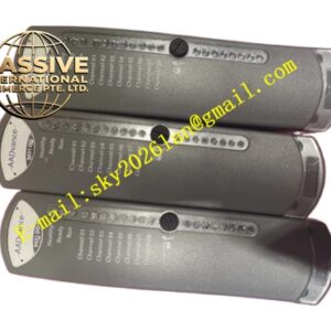
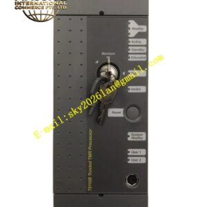
ICS Triplex‑T8831 Analog Output Module
Technical Specifications:
- Output Signal Standard: 4‑20 mA analog current output
- Channel Quantity: 4 analog output channels
- Output Load Resistance Range: 0‑750 Ω per channel
- Output Accuracy: ±0.15 % full scale
- Conversion Resolution: 16‑bit digital‑to‑analog conversion
- Galvanic Isolation: 2500 VDC isolation between field output circuit and internal logic circuit
- Backplane Power Supply: 24 VDC from Trusted rack power unit
- Operating Temperature: 0 °C ~ +60 °C
- Storage Temperature: −40 °C ~ +85 °C
- Relative Humidity: 5 %‑95 %, non‑condensing
- Vibration Resistance: 2 g, 10‑500 Hz
- Shock Resistance: 15 g, 11 ms duration
- Net Weight: 0.75 kg
- Certifications: SIL 3, ATEX, IECEx, CE
Functional Features:
- Full TMR triple‑channel redundant analog output, hardware voting ensures output value validity
- Per‑channel load fault diagnosis, detect open‑circuit and short‑circuit field output loop
- Independent LED status indicator for each output channel
- 16‑bit DAC conversion delivers high‑precision analog output
- Hot‑swap compatible under approved Trusted system configuration
- Supports configurable fail‑safe output state under module or system fault condition
- Real‑time fault diagnostic information upload to Trusted main controller
Application Scenarios: Safety‑related analog valve control, petrochemical process modulating safety loops, power plant safety auxiliary control, chemical plant reactor analog regulation, offshore platform safety instrument system analog output control.
Material Composition:
- Module frame: Flame‑retardant metal‑plastic composite structural frame
- Circuit substrate: Conformal coated multi‑layer industrial grade PCB, high‑precision DAC components
- Field connection: Screw‑type locking spring terminal blocks
- Backplane connector: Gold‑plated 96‑pin industrial connector
- Fasteners: Stainless steel anti‑vibration locking parts
Structural Characteristics: Standard Trusted rack‑mount module dimension. Front panel arranges channel LED indicators and analog output terminal blocks. Rear side mounts 96‑pin backplane mating connector. Internal metal shielding separates analog output circuits and digital logic circuits. Dual side spring latches lock module into rack slots firmly.
Working Principle: Main processor sends target digital output value to three independent TMR channels. Each channel executes digital‑to‑analog conversion. Hardware voting circuit validates three analog signals and generates final 4‑20 mA output current. On‑board diagnostic circuits continuously sample output loop voltage and current to identify open‑circuit and short‑circuit conditions. Measurement and fault status transmit to main controller through rack backplane bus.
Installation Requirements:
- Insert T8831 module into designated slot of Trusted rack assembly.
- Fully engage side locking latches to guarantee complete backplane connector contact.
- Use shielded twisted‑pair cables for all analog output field wiring. Implement single‑point shield grounding.
- Calculate total loop resistance, ensure loop resistance stays within 0‑750 Ω specification range.
- Connect rack protective earth terminal to plant safety grounding network.
Usage Notes:
- Total loop resistance cannot exceed maximum rated load resistance. Over‑load causes output signal distortion.
- Analog output cables shall be routed separately from high‑voltage power cables to reduce electromagnetic coupling interference.
- Configure correct fail‑safe output value in system software according to process safety requirement before commissioning.
- Verify field loop polarity at wiring stage. Reverse polarity results in field device malfunction.
- Follow official operation manual strictly while performing module hot‑swap operations.