Description
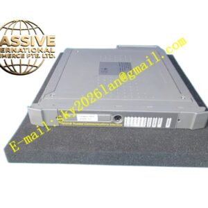
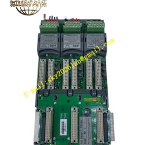
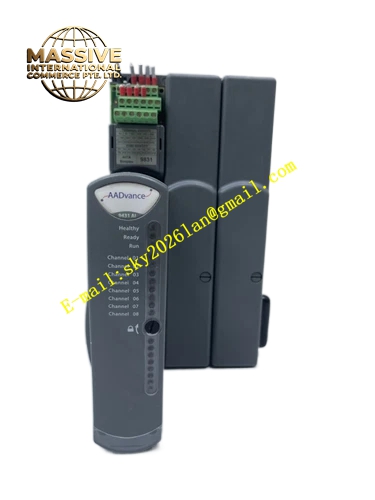
ICS Triplex T9431
Technical Specifications
| Parameter | Specification |
|---|---|
| Part Number | T9431 |
| Manufacturer | ICS Triplex (Rockwell Automation) |
| Series | AADvance System |
| Type | Isolated Analogue Input Module |
| Channel Capacity | 8 fully isolated analog input channels |
| Nominal Signal Range | 4 mA to 20 mA DC |
| Maximum Measurement Range | 0 mA to 24 mA DC |
| Analog Resolution | 15-bit resolution (LSB value: 0.98 µA) |
| Isolation | Withstands up to ±1.5 kV DC for 1 minute (channel-to-channel and field-to-logic) |
| System Architecture | Configurable as 2oo3D, 1oo2D, or 1oo1D voting |
| Line Monitoring | 5 configurable voltage bands per channel with 8 distinct switching thresholds |
| HART Support | HART commands (Command #03) pass-through for field device diagnostics |
| Power Dissipation | 3.3 W (11.3 BTU/hr) on redundant +24 VDC nominal system lines |
| Operating Voltage | 18–32 VDC |
| Configuration Tool | AADvance Workbench software |
Functional Features
-
Eight Isolated Channels: Each channel galvanically isolated from others and from system logic
-
High-Resolution Measurement: 15-bit A/D conversion provides precise current measurement
-
HART Protocol Integration: Supports HART pass-through for smart transmitter diagnostics and asset management
-
Flexible Redundancy: Configurable in Simplex, Dual-Redundant, or TMR architectures
-
Advanced Line Monitoring: Configurable voltage bands and switch thresholds detect open circuits and wiring faults
-
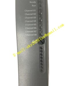
Front-Panel LEDs: Channel-level and module-level LED diagnostics for easy monitoring
-
Software Configuration: Full integration with AADvance Workbench for setup and diagnostics
Application Scenarios
-
Process pressure measurement in safety loops
-
Temperature transmitter signal acquisition
-
Flow meter monitoring in pipeline safety systems
-
Level transmitter interfaces for tank safety
-
Analytical instrument signal conditioning
-
Critical continuous parameter monitoring in SIS
Performance Parameters
-
Measurement Accuracy: 15-bit resolution with 0.98 µA least significant bit
-
Isolation Strength: 1.5 kV DC withstand capability
-
Fault Degradation: Seamless transition through 2oo3D, 1oo2D, and 1oo1D configurations
-
HART Communication: Reliable pass-through of HART digital signals superimposed on 4–20 mA
Material Composition
-
Enclosure: Industrial-grade housing suitable for control cabinet installation
-
Circuit Board: Multilayer PCB with precision analog front-end circuits
-
Isolation Barriers: High-voltage isolation components for channel and field protection
-
Connectors: Industrial-grade backplane and field terminal connectors
Structural Characteristics
-
AADvance Module Form Factor: Standard size for AADvance controller chassis
-
Front-Panel Indicators: LED status lights for each channel and module health
-
High-Density Design: Eight channels in a compact module footprint
-
Modular Architecture: Supports system expansion through additional modules
Working Principle
Each of the eight input channels receives a 4–20 mA current signal from a field transmitter. The current passes through a precision sense resistor to generate a voltage for A/D conversion. Three independent A/D converters (in TMR mode) simultaneously measure each signal. The voter compares results and outputs the validated measurement to the AADvance controller. HART digital signals are extracted from the analog loop and passed to the asset management system. Line monitoring circuits continuously verify field wiring integrity.
Installation Requirements
-
Install in an AADvance controller chassis
-
Use shielded twisted-pair cables for field connections
-
Ensure proper grounding of cable shields
-
Configure voltage bands and thresholds via AADvance Workbench
-
Verify isolation integrity during commissioning
Operating Precautions
-
Calibrate channels periodically to maintain measurement accuracy
-
Monitor diagnostic flags for field wiring degradation
-
Verify HART communication integrity when using smart transmitters
-
Replace failed modules according to AADvance maintenance procedures
-
Maintain proper environmental conditions within specified ranges