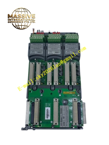
Description
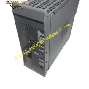
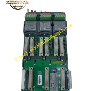
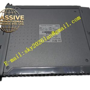
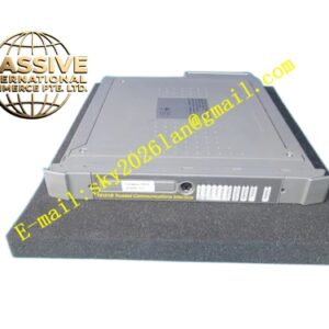
ICS Triplex T9802
Technical Specifications & Performance Parameters:
- Supported Signal Type: 24 VDC discrete digital input
- Channel Quantity: 16 field input channels
- Input Signal Threshold: 10 VDC logic low, 18‑32 VDC logic high
- Per‑Channel Input Current: 4‑7 mA
- Galvanic Isolation Rating: 2500 V RMS reinforced channel‑to‑backplane isolation
- Power Consumption: Max 5.8 W
- Protection Mechanisms: Channel‑level surge‑suppression, over‑voltage clamping, reverse‑voltage protection
- Safety Certification: TÜV IEC 61508 SIL 3, UL, CE
- Operating Temperature: ‑20 °C ~ +60 °C
- Storage Temperature: ‑40 °C ~ +85 °C
- Ambient Humidity: 5 %‑95 % RH non‑condensing
- Weight: 0.58 kg
- Form Factor: DIN‑rail‑mounted cabinet‑internal field termination assembly
Functional Features:
- High‑density 16‑channel field‑signal physical transition for Trusted TMR digital‑input modules
- Independent per‑channel surge‑suppression circuit, restrain transient voltage disturbance on field cables
- High‑voltage reinforced galvanic‑isolation barrier, isolate field‑side ground‑loop noise
- Screw‑type high‑torque wiring terminal blocks, support batch field‑cable wiring
- Dedicated ribbon‑cable realizes signal link between T9802 and Trusted rack‑mounted digital‑input module
- Front‑panel LED indicator array, display real‑time on‑off state of each input channel
- Optimized compact layout, save cabinet DIN‑rail installation space
- All safety‑related signal voting and diagnostic logic run on rack‑side TMR I/O module; T9802 only completes signal conditioning work
Working Principle: Field 24 VDC switch signals get connected to T9802 16‑way screw‑type terminals. Each input channel passes surge‑absorption component and optocoupler isolation circuit. Conditioned digital signals transmit through dedicated ribbon‑cable to rack‑mounted TMR digital‑input module. Rack‑side module executes triple‑modular signal sampling and hardware 2‑out‑of‑3 voting. Front‑panel LED indicators reflect real‑time field‑signal state. T9802 does not participate in safety‑logic operation, only realizes signal isolation and wiring transfer.
Material Composition & Structural Characteristics:
- Housing: Flame‑retardant high‑strength ABS engineering plastic housing
- Circuit substrate: Multi‑layer FR‑4 industrial printed circuit board, integrate multi‑channel isolation and surge‑protection components
- Field connection: Screw‑type anti‑loosening wiring terminal blocks
- Internal interconnection: Gold‑plated high‑density ribbon‑cable connector
- Front panel: Embedded multi‑channel LED indicator group and channel‑number marking area, protection grade IP20
Installation Requirements:
- Mount T9802 on standard DIN‑rail inside control cabinet, keep close distance with matched Trusted I/O rack
- Deploy factory‑specified dedicated ribbon‑cable for connection between and rack‑side digital‑input module
- Field input cables adopt shielded twisted‑pair cables, keep physical separation distance with high‑voltage power cables
- Cable shielding layer single‑end grounding at cabinet ground bus‑bar
- Cabinet protective ground resistance ≤4 Ω
- Avoid ribbon‑cable crossing high‑power‑equipment wiring area to prevent electromagnetic interference
- Do not install in environment with heavy salt‑fog and corrosive‑gas
Application Scenarios:
- Large‑quantity discrete‑switch signal termination for petrochemical ESD safety‑system
- Chemical complex multi‑workshop safety‑interlock field‑status‑signal access
- Fire‑gas detection system multi‑point discrete detector‑signal physical interface
- Off‑shore platform distributed safety‑switch signal centralized wiring transition
- Power‑plant safety‑shutdown system multi‑equipment status‑signal termination
Usage Notes:
- Disconnect field‑side power supply before carrying out field‑wiring modification
- Do not use non‑standard ribbon‑cables for interconnection with Trusted I/O module
- Module shell disassembly is forbidden; no internal user‑maintainable spare parts
- After cable modification or module replacement, verify each channel LED status consistency with actual field‑device state
- Operate strictly within rated operating temperature range
- Periodically inspect wiring‑terminal fastening torque and cable insulation condition