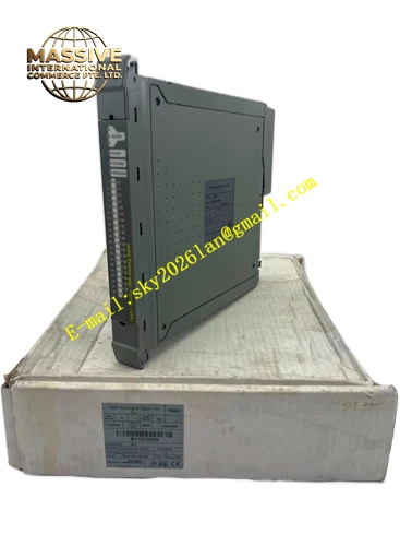
Description
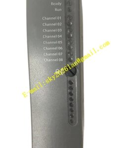
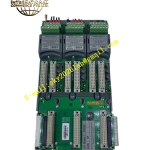
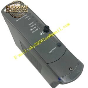
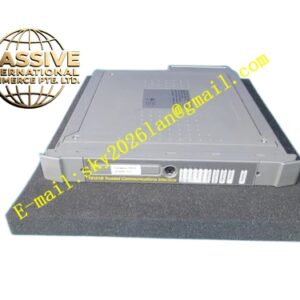
ICS Triplex T9852
Technical Specifications:
- Field Connections: 8 channels
- Wiring: Conductor cross-section maximum 1.31 mm² (16 AWG)
- Stripping Length: 6 mm (¼ in.)
- Modules Supported: Two digital output modules
- Field Supply Fuses: 10 A for each field supply
- Dimensions (HxW): 132 mm x 84 mm (5-¼ in. x 3-5/16 in.)
- Weight: 260 g (10 oz.)
- Configuration: Dual 8-channel output termination
Functional Features:
- Eight field connection points for digital output devices
- Dual module support enabling connection to two output modules
- Replaceable 10 A field supply fuses for each power source
- Standard terminal block design accepting up to 16 AWG conductors
- Coding peg configuration preventing incorrect module mating
- Separate field power input voltage connections
Application Scenarios:
- Solenoid valve control circuit termination
- Motor contactor coil driving
- Alarm and indicator light control
- Pump and fan start/stop circuits
- Heater element switching interfaces
- Emergency shutdown device actuation
Performance Parameters:
- Current Rating: 10 A fuse protection per field supply
- Wire Capacity: Up to 1.31 mm² (16 AWG)
- Channel Count: 8 output channels per assembly
- Module Capacity: Supports two connected modules
Material Composition:
- Housing: Industrial-grade polymer or metal enclosure
- Terminal Blocks: High-current screw terminals
- Fuses: 10 A replaceable field supply fuses
- PCB: Conformal coated for environmental durability
Structural Characteristics:
- Compact vertical form factor for DIN rail mounting
- Dual-section layout supporting two module connections
- Fuse holders accessible for replacement without disassembly
- Clear terminal numbering and polarity marking
- Coding pegs ensuring correct module insertion
Working Principle: The T9852 receives digital output commands from connected AADvance digital output modules through internal bus connections. The output signals are routed to field terminals where external devices connect. Each field power source passes through a 10 A fuse for protection against short circuits and overloads. The dual configuration allows two modules to share the termination assembly for high-density applications.
Installation Requirements:
- Mount on standard DIN rail in control cabinets
- Connect field wiring using conductors maximum 1.31 mm²
- Maintain 6 mm stripping length for proper terminal engagement
- Install appropriate 10 A fuses in field supply circuits
- Verify coding peg alignment before module installation
Usage Precautions:
- Replace fuses only with 10 A rating to maintain protection
- Do not exceed wire gauge capacity of terminal blocks
- Verify field device voltage compatibility before connection
- Inspect fuse holders periodically for proper contact
- De-energize field power before performing wiring changes