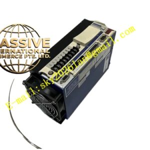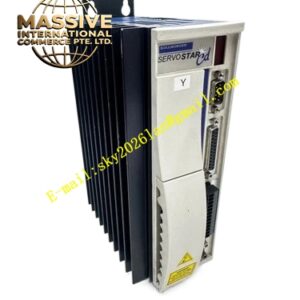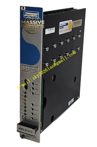
Description
Kollmorgen 60WKS-CE240 12PB
Technical Specifications
- Series: 60WKS Analog Servo Amplifier Series
- Input Voltage: Three-phase 60 to 172 VAC, 50/60 Hz with plus or minus 10 percent tolerance
- Rated DC-Link Voltage: 240 VDC
- Peak Output Current: 12 Amps
- Continuous Output Current: 6 Amps
- Rated Power: 2.0 kVA
- Ballast Circuit Pulse Power: 5.4 kW
- Ballast Circuit Continuous Power: 135 W
- Control Method: Analog PI current and speed control
- Commutation: Trapezoidal commutation for brushless motors
- Feedback: RLG resolver and DC tachometer inputs
- Logic Interface: 24 VDC with isolated optocouplers, PLC-compatible
- Protection: Overvoltage, undervoltage, overcurrent, and thermal monitoring of power transistors
- Operating Temperature: 0 degrees Celsius to plus 40 degrees Celsius
- Protection Rating: IP00, requires installation in closed switchgear cabinet
- Humidity: 5 percent to 85 percent relative humidity
Functional Features
- Three-phase PWM transistor output stage for 4-quadrant operation
- Two differential setpoint inputs with individual adjustment capability
- Enable input for secure system integration
- Electronic rotor position sensor input for phase switching control
- Ballast circuit with characteristic-w for power-sharing between parallel modules
- Ready/standby relay with isolated contact for fault signaling
- LEDs indicating all important operating states
- Expansion slot for optional limit-switch logic and ramp generator PCB
- Custom printed circuit board containing user-adjustable parameters
Application Scenarios
- Legacy CNC machine tools
- Industrial robotics retrofits
- Packaging machinery
- Printing equipment
- Automated assembly lines using SM series servo motors
Performance Parameters
- 200 kilohertz current loop bandwidth for fast dynamic response
- 16-bit resolution for precise position and speed control
- Smooth trapezoidal current output for reliable motor commutation
- Stable operation under varying load conditions through PI control
Material Composition and Structure
- Steel chassis with aluminum front panel
- Modular internal architecture with plug-in custom PCB
- Heavy-duty terminal blocks for power and motor connections
- Integrated smoothing capacitors and ballast resistor
- Status LED indicators for operational monitoring
Working Principle The amplifier receives analog setpoint signals through differential inputs and compares them against actual motor speed from the tachometer feedback. PI controllers regulate motor speed and trapezoidal output current. The electronic rotor position sensor controls phase switching of the motor and tacho windings. The three-phase PWM transistor stage delivers power to the motor in four-quadrant operation, allowing both motoring and regenerative braking.
Installation Requirements
- Install in closed steel switchgear cabinet maintaining 0 to 40 degrees Celsius ambient
- Connect to three-phase isolating transformer supplying 60 to 172 VAC
- Use shielded and twisted cables for setpoint, tacho, and motor connections
- Earth the DC-link circuit through pin 28 or stud to GND/PE
- Ensure all earth leads connect to a common PE busbar to avoid ground loops
Operating Precautions
- Never connect or disconnect while system is live
- Wait 120 seconds after power-off before servicing as capacitors retain residual charge
- Measure DC-link voltage and confirm it has fallen below 20 VDC before touching terminals
- Ensure adequate ventilation, vertical mounting required for natural convection
- Use armature chokes and ferrite rings if interference occurs in CNC systems