Description
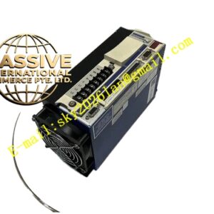
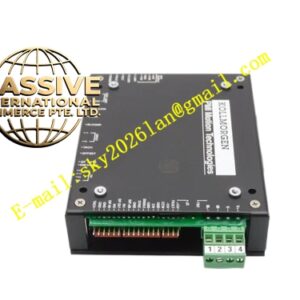
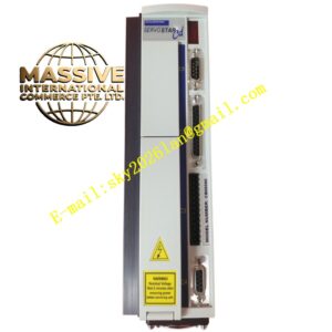
Kollmorgen controller prd‑mz40asiz‑62
Technical Specifications: Single‑phase 120‑240 VAC input; continuous output current 4 Arms; peak output current 8 Arms; switching frequency 8 kHz; DC‑bus voltage 325 VDC; ±10 V analog command input; pulse‑direction position command input; support SFD smart feedback and incremental encoder; optically‑isolated multi‑channel digital IO; RS232 debugging interface; operating temperature 0 ℃‑55 ℃; storage temperature ‑20 ℃‑85 ℃.
Functional Features: Torque‑velocity‑position full three‑loop closed‑loop control; SFD motor automatic identification; electronic gear ratio function; encoder emulation output; automatic loop tuning; hardware fault latch output; external limit, home and drive‑enable signal processing; fault relay contact output.
Application Scenarios: Medium‑small electronic assembly machinery, vintage packaging equipment, test fixture platforms, spare‑part replacement for imported automated devices.
Performance Parameters: Maximum pulse command receiving frequency 1 MHz; I²T thermal overload protection; hardware protection for over‑current, DC‑bus over‑voltage, DC‑bus under‑voltage, over‑temperature and feedback‑signal loss.
Material Composition: Die‑cast aluminum alloy housing; IGBT power semiconductor modules; gold‑plated industrial connectors; flame‑retardant PCB circuit board; integrated metal heat‑sink fins; internal cooling fan assembly.
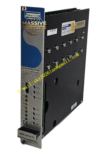
Structural Features: DIN‑35 rail book‑style housing; front‑panel LED status indicator lights; DIN‑rail locking clip on rear side; power terminals, feedback connectors and IO terminals distributed on rear section; forced‑air cooling by internal fan.
Working Principle: Single‑phase AC input is rectified to DC‑bus voltage. Power inverter outputs three‑phase AC to drive servo motor. Feedback signal is collected and converted into digital value for three‑loop closed‑loop algorithm calculation. Drive responds to external analog voltage or pulse‑direction motion commands. Hardware monitoring circuits detect equipment operating status, and shut down power‑stage output once fault condition occurs.
Installation Requirements: Vertically mount on standard DIN‑35 rail inside control cabinet; maintain 25 mm upper‑lower ventilation clearance and 10 mm left‑right clearance; separate power‑cable routing and signal‑cable routing; connect unit protective‑earth terminal to cabinet grounding bar reliably; keep cabinet under IP20 protection condition.
Usage Notes: Live hot‑swap of internal circuit boards is forbidden; wait for DC‑bus full discharge before maintenance work; ambient operating temperature shall not exceed 55 ℃; spare‑part replacement must verify SFD motor parameters and wiring definition consistency.