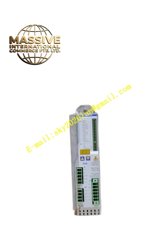
Description
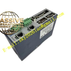
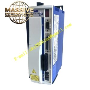
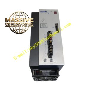
Kollmorgen S30101
Technical Specifications
- Product Family: SERVOSTAR 300
- Brake Circuit Threshold: S303 overvoltage F02
- Internal Brake Resistor (RBint): 66 Ohm
- Continuous Power for Internal Resistor: 20 W
- Max Brake Power (average for 1s): 0.4 kW
- Pulse Brake Power: 0.84 kW
- External Brake Resistor (RBext) Continuous Power: 0.3 kW
Functional Features
- Digital Servo Amplification: Functions as a drive unit within a closed-loop servo system
- Integrated Brake Circuit: Includes internal brake resistor for dynamic braking
- External Brake Resistor Support: Compatible with external brake resistors for higher braking demands
Application Scenarios
- Industrial Automation: Production line control, material handling, packaging machinery
- Machine Tools: CNC machine tools, cutting equipment
- Medical Equipment: Medical imaging devices, surgical robots, rehabilitation equipment
- Semiconductor Manufacturing: Precision positioning in semiconductor production equipment
Performance Parameters
- Internal Brake Resistor Value: 66 Ohm
- Continuous Resistor Power Rating: 20 W
- Max Average Brake Power (1s): 0.4 kW
- Pulse Brake Power: 0.84 kW
- External Resistor Continuous Power: 0.3 kW
Material Composition
- Metal housing with integrated electronic components including brake resistor circuit
Structural Features
- Brake Circuit Integration: Built-in brake circuit with internal resistor
- External Resistor Connection: Provision for connecting external brake resistor
Working Principle
The S30101 operates as part of a servo system. The drive powers the servo motor, while a feedback device monitors the rotor’s rate and position. The drive receives these signals through its control circuit and continuously adjusts the current and voltage supplied to the motor, correcting deviations in real time to ensure precise execution of programmed motion.
Installation Requirements
- Mounting inside a closed switchgear cabinet
- Proper EMC-compliant grounding required
- External fusing required for AC supply protection
- Suitable external brake resistors must be selected from Kollmorgen’s accessories if internal braking capacity is insufficient
Usage Notes
- Verify motor voltage and current ratings match the drive specifications
- Monitor thermal conditions during continuous operation
- Back up drive configuration parameters regularly
- Wait for DC bus voltage to drop below safe levels before handling components after power disconnection