Description
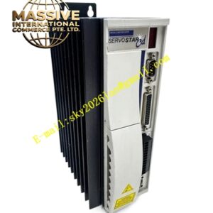
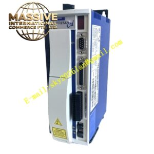
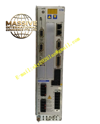
Kollmorgen S70601-FN2
- Technical Specifications:
- Series: ServoStar 700 (S700), S706 sub-series
- Type: Digital servo amplifier
- Rated Line Power: 4.5 kVA (S1 operation)
- Rated Output Current: 6 Arms at 1×110 V / 1×230 V / 3×208 V / 3×230 V; 6 Arms at 3×400 V; 6 Arms at 3×480 V
- Peak Output Current: 18 Arms
- Input Voltage: 1×110 V–230 V or 3×208 V–480 V, 50/60 Hz
- DC Bus Voltage: 290–675 VDC
- Auxiliary Power: 24 VDC
- Functional Features:
- Multi-mode servo control: torque, velocity, position, and programmable positioning
- Onboard EtherCAT and CANopen fieldbus communication
- Dual-channel STO safety function (SIL2/PLd)
- Multi-feedback support: resolvers, SinCos encoders (BiSS, EnDat, HIPERFACE), incremental encoders, Hall sensors
- Integrated autotuning with oscilloscope and Bode plot display
- IEC 61131-3 macro programming (128 KB code memory, 62.5 µs cycle time)
- Internal brake resistor and EMC filter
- Dynamic braking circuit for regenerative energy dissipation
- Application Scenarios:
- Heavy-duty CNC machinery and precision machining
- Industrial robotics and gantry systems
- Automated assembly and material handling
- Semiconductor manufacturing equipment
- Performance Parameters:
- Current loop update rate: 62.5 µs
- Velocity loop update rate: 62.5 µs
- Position loop update rate: 250 µs
- PWM switching frequency: 8 kHz
- Peak current capability: 3× continuous rating for short bursts
- Material Composition:
- Industrial-grade metal housing with enhanced heat dissipation
- IGBT-based power stage with protective circuitry
- Internal EMC filter and dynamic braking components
- Structural Features:
- Panel-mount enclosure with standard industrial I/O connectors
- Embedded LED status display for diagnostics
- MMC storage card slot for parameter backup and firmware updates
- RS232 interface for full programming via PC
- Working Principle:
- Digital closed-loop servo control with PID regulation across current, velocity, and position loops. The drive processes motion commands, compares them with motor feedback, and modulates PWM output to achieve precise control. The integrated dynamic braking circuit safely dissipates regenerative energy during rapid deceleration.
- Installation Requirements:
- Mount in a well-ventilated control cabinet with adequate thermal management
- Use shielded cables for motor power, feedback, and fieldbus connections
- Ensure proper grounding and equipotential bonding
- Maintain minimum clearance for airflow
- Usage Notes:
- The “FN2” suffix indicates a specific feedback/network interface configuration — verify compatibility with the connected motor and controller
- Monitor drive temperature during sustained heavy-load operation
- This is a legacy product; verify spare parts availability before procurement