Description
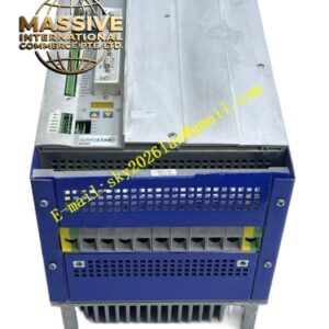
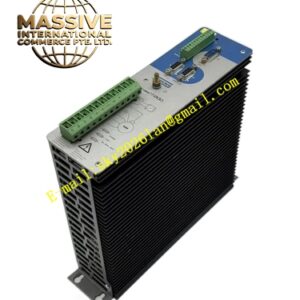
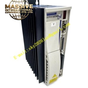
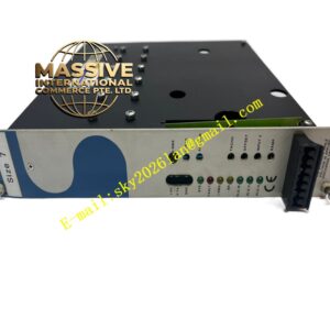
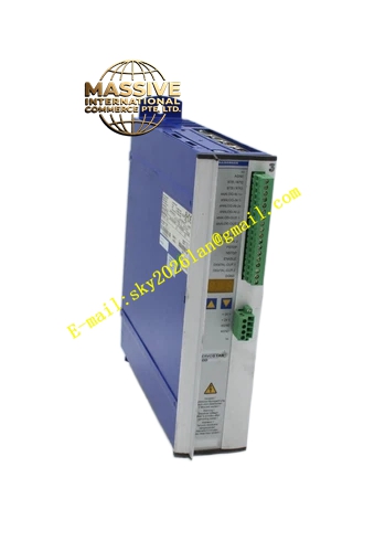
Kollmorgen S77202‑NANANA
Technical Specifications: ‑ Input Power Supply: 3‑phase 208‑480 VAC ‑ Continuous Output Current: 72 A RMS ‑ Peak Output Current: 144 A RMS for 5 seconds ‑ Control Supply Voltage: 24 V DC ±20% ‑ Safety Function: Dual‑channel Safe Torque‑Off STO SIL2 PL d ‑ Fieldbus Interfaces: EtherCAT, CANopen; supports expansion for PROFINET, DeviceNet ‑ Feedback Interfaces: EnDat 2.2, BiSS‑C, HIPERFACE, resolver, SFD3 single‑cable feedback ‑ Digital Inputs: 6 optically isolated digital inputs ‑ Digital Outputs: 2 optically isolated digital outputs ‑ Analog Inputs: 2 analog inputs ±10 V ‑ Analog Outputs: 2 analog outputs ±10 V ‑ Memory Medium: MMC memory card slot ‑ Cooling Method: Forced air convection cooling ‑ Installation Form: DIN‑rail cabinet mounting ‑ Operating Ambient Temperature: 0 °C to +55 °C ‑ Storage Temperature: ‑25 °C to +70 °C ‑ Protection Class: IP20 cabinet‑installation only ‑ Compliance Certification: CE, UL, RoHS, REACH
Functional Features: ‑ High‑current power stage supports large‑torque motor for heavy‑load acceleration and deceleration cycles ‑ Dual‑channel hardware STO safety function achieves safe torque removal without main‑circuit power cut‑off ‑ Compatible with synchronous, asynchronous, spindle and linear motor types ‑ Supports SFD3 single‑cable feedback to reduce wiring workload ‑ IEC 61131‑3 macro programming realizes custom motion logic inside drive ‑ MMC memory card supports parameter backup, restore and firmware batch update ‑ Built‑in high‑power brake chopper handles large‑magnitude regenerative energy from heavy‑load deceleration ‑ Comprehensive fault diagnosis covers over‑current, over‑voltage, under‑voltage, over‑temperature, motor short‑circuit, feedback‑signal loss ‑ Front‑panel LED indicators directly display operating status, warning and fault information ‑ Full configuration supported via Kollmorgen WorkBench software
Application Scenarios: Used for heavy‑duty industrial equipment: large‑size gantry machines, heavy‑duty packaging lines, metal‑processing auxiliary axes, material test benches, large‑format printing presses, heavy‑duty robotic joint drives. Installed inside industrial control cabinets for general factory automation environments.
Performance Parameters: ‑ Current loop bandwidth: Max 3.5 kHz ‑ Velocity loop bandwidth: Max 700 Hz ‑ Position loop bandwidth: Max 220 Hz ‑ Supports high‑resolution encoder feedback up to 23‑bit ‑ Short‑circuit protection response time less than 2 μs ‑ STO safety response time below 2 ms ‑ Pulse‑direction command input maximum frequency reaches 1 MHz
Material Composition: ‑ Main housing: Cold‑rolled steel sheet with black powder‑coated surface ‑ Power module substrate: Insulated metal substrate for power semiconductors ‑ Power devices: High‑current IGBT power switches ‑ Signal circuit board: FR‑4 glass‑epoxy printed circuit board ‑ Terminal blocks: Flame‑retardant nylon plastic with tin‑plated copper contacts ‑ Heat sink: Large‑size extruded aluminum alloy ‑ Front‑panel cover: Polycarbonate flame‑retardant plastic
Structural Features: ‑ Vertical DIN‑rail mounting cabinet‑type structure, rear bottom side equipped with standard DIN‑rail clamping buckle ‑ Physical separation layout between high‑power power circuit region and low‑voltage signal circuit region to suppress electromagnetic interference ‑ Front‑side accessible terminal blocks for power supply, motor power, feedback signal and analog‑digital I/O ‑ Front‑mounted LED indicator group and MMC card slot ‑ Large‑volume aluminum heat sink behind power module, forced‑air cooling channel independent of signal board area ‑ Reserved expansion slots for optional communication interface modules.
Working Principle: Three‑phase AC input passes internal rectifier to generate DC bus voltage. High‑current IGBT inverter converts DC bus to adjustable‑frequency adjustable‑amplitude three‑phase AC output to drive motor. Motor position and velocity feedback signal feeds back to drive control board. Digital processor executes closed‑loop position, velocity and torque control algorithm according to host command. Dual‑channel STO hardware circuit cuts IGBT gate drive signal to remove motor torque under safety trigger condition. Integrated brake chopper consumes regenerative energy produced by heavy‑load deceleration to stabilize DC bus voltage.