Description
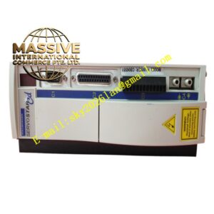
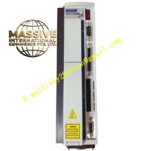
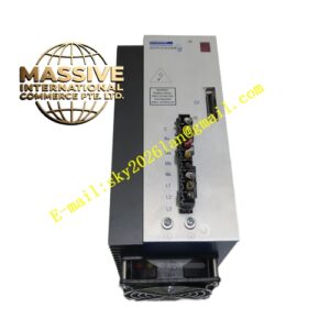
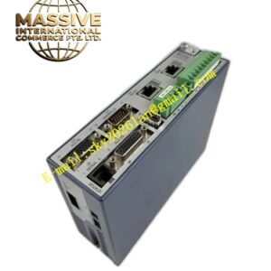
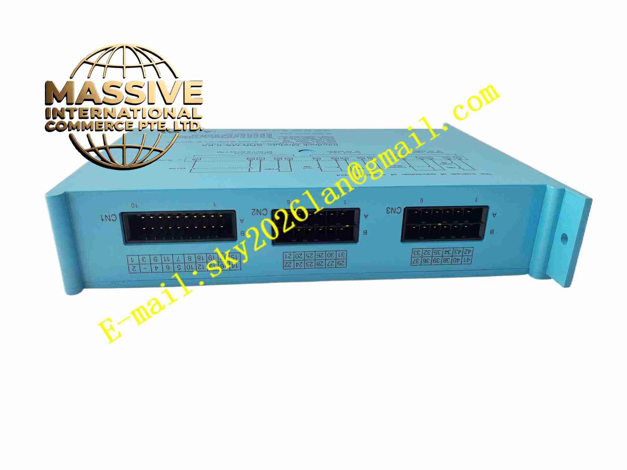
KOLLMORGEN SRB-MS-ILK5
Technical Specifications Brand: Kollmorgen Model: SRB-MS-ILK5 Power Supply: 24 VDC Brake Control Output: Regulated DC output for motor holding brake coil Signal Interface: Digital logic interface connecting to servo drive Operating Temperature: 0°C to +55°C Humidity: 10% to 90% non-condensing Mounting: DIN rail mounting Protection Grade: IP20 cabinet mounting
Functional Features Synchronizes brake release and engage timing with servo drive enable signal. Current regulation for brake coil to reduce thermal consumption during brake holding state. Circuit fault detection monitors brake coil open circuit and short circuit condition. Digital status feedback signal transmits brake state to servo controller. Overvoltage and overcurrent protection built in brake output channel. Supports multiple servo motor brake control configuration in multi-axis systems.
Application Scenarios Vertical axis CNC machine servo control, gantry robot suspended axis, automated warehouse lifting mechanism, packaging machine vertical moving axis, material handling lifting servo system.
Performance Parameters Precise timing coordination between brake action and motor torque enable. Continuous monitoring of brake coil circuit integrity. Stable brake coil current regulation under input voltage fluctuation. Instant fault reporting when brake circuit failure occurs. Consistent brake switching performance over long operation cycles.
Material Composition Housing: Flame-retardant plastic DIN rail casing. PCB: FR4 multilayer printed circuit board with protective coating. Core Components: Power switching semiconductor, current sampling circuit, logic control chip, fault detection circuit, surge protection devices. Terminals: Tin-plated copper screw terminals.
Structural Features Compact rectangular DIN rail mount housing. Front panel carries terminal marking and status LED indicators. Rear integrated spring clip for attachment to standard DIN rail. Internal layout separates low-voltage logic signal part and brake power output circuit. Front screw terminal blocks for brake coil wiring and control signal wiring.
Working Principle The module receives brake enable command signal from Kollmorgen servo drive. When motor is ready for rotation, module outputs regulated DC current to energize brake coil and release mechanical brake. When servo drive disables motor torque, module cuts brake coil power supply, spring force engages brake to lock motor shaft. Monitoring circuit continuously samples brake coil current to judge coil open or short fault and sends fault signal back to servo controller.
Installation Requirements Mount module on 35mm DIN rail inside control cabinet close to servo drive. Use twisted pair cable for brake coil wiring. Route brake power wiring separately from encoder signal cables. Connect 24VDC power and control signal wiring to corresponding terminals. Set brake action delay parameter inside servo drive after wiring completion. Test brake release and lock sequence before load operation.
Usage Notes Disconnect power supply before wiring modification. Do not connect brake coil load exceeding module rated capacity. Check brake cable insulation integrity periodically. Verify brake timing parameter after servo system commissioning. Prevent dust accumulation on module surface inside cabinet.