Description
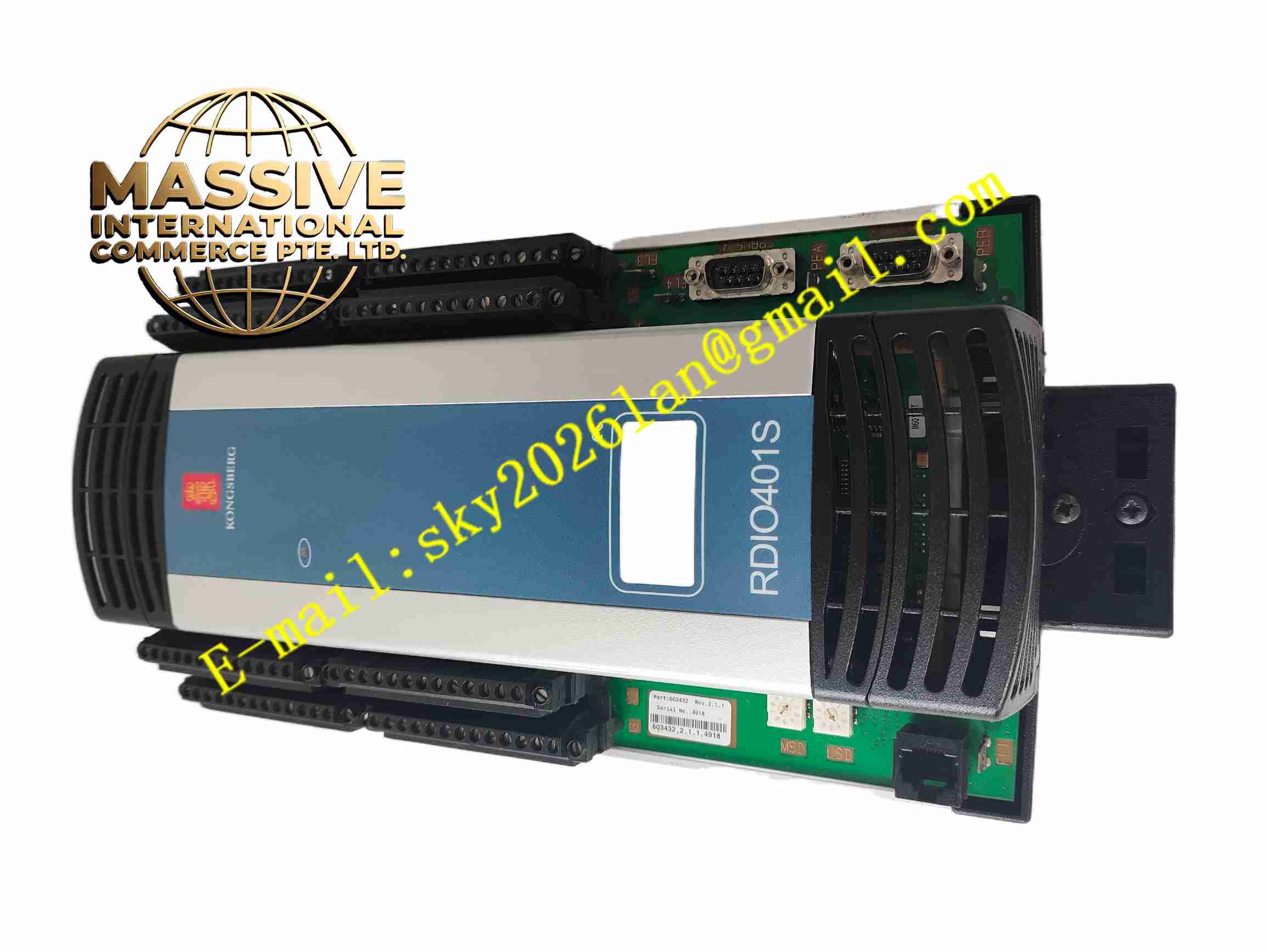
KONGSBERG RDIO401S 603432
Technical Specifications Model: RDIO401S Part Number: 603432 Brand: Kongsberg Power Supply: 24V DC marine auxiliary power Input Type: Multi-channel digital input for dry contact signals Output Type: Multi-channel digital output relay or transistor channel Communication: Marine fieldbus interface Operating Temperature: -10 ℃ ~ +55 ℃ Storage Temperature: -25 ℃ ~ +70 ℃ Relative Humidity: 10% ~ 95%, non-condensing Mounting: NS35 DIN rail mounting Protection Grade: IP20 Vibration Standard: Complies with marine classification society vibration specification
Functional Features Multi-channel digital input reads dry contact status of limit switches, pressure switches and alarm contacts. Digital output channels drive marine solenoid valves, alarm lamps and auxiliary relays. Onboard self-diagnosis monitors channel wiring fault and module hardware abnormality. Fieldbus communication transmits digital status data to main controller and receives control command. Front panel LED indicators display power, running status, communication state and channel fault. Non-volatile memory stores module station address and configuration data. Surge protection circuit protects signal channels from transient voltage surge on marine power network. Supports module status upload to ship central alarm monitoring system.
Application Scenarios Ship valve status monitoring, pump start-stop control, fire and gas detector contact signal collection, marine machinery alarm signal acquisition, offshore platform equipment on-off control, vessel auxiliary equipment interlock logic system.
Performance Parameters Digital input reliably recognizes contact open and closed state under hull vibration. Digital output maintains stable driving capacity for rated field load. Self-diagnosis function detects channel short circuit or open circuit fault accurately. Fieldbus communication maintains stable data transmission under marine electromagnetic environment. Configuration data remains stored after power supply interruption. Surge protection circuit suppresses transient voltage spikes and protects internal chip.
Material Composition Housing: Flame-retardant black plastic front panel and metal shielding frame. Main PCB: FR4 multi-layer printed circuit board with moisture-proof conformal coating. Core Electronic Components: Microcontroller, digital input protection chips, relay chips, bus transceiver, surge suppression components, non-volatile memory. Terminal Parts: Vibration-resistant copper alloy screw terminals. Indicator Components: LED status indicators on front panel. Fasteners: Stainless steel anti-corrosion screws and DIN rail spring clip.
Structural Features Compact rectangular DIN rail module structure for marine control cabinet installation. Front panel carries LED indicators and module part number marking. Rear screw terminals for 24V power, fieldbus, digital input and digital output wiring. Metal shielding frame reduces electromagnetic interference. Internal circuit separates input signal circuit, output drive circuit and bus communication circuit. Vibration reinforced soldering process improves mechanical reliability under hull vibration.
Working Principle 24V DC marine power supplies RDIO401S module. Dry contact signals from field marine switches are connected to digital input terminals. The digital input circuit detects open or closed state of contact signal and converts state into digital logic signal. The onboard microcontroller collects all channel status data and transmits data to main automation controller through marine fieldbus. When receiving control command from main controller, module activates digital output channel to energize or de-energize field solenoid valves and indicator lamps. Self-diagnosis circuit continuously monitors channel state and module hardware. Once fault is detected, fault LED lights up and fault information is uploaded to main marine control system.
Installation Requirements Install RDIO401S inside dry marine control cabinet on NS35 DIN rail. Connect 24V DC marine power supply, fieldbus cable and field contact cables to corresponding terminals. Use shielded twisted pair cable for fieldbus wiring. Complete protective earth grounding to ship grounding system. Set module station address in Kongsberg automation configuration software. Test all digital input and output channels after wiring completion. Keep module away from high-power inverter and motor cables.
Usage Precautions Check terminal screw tightness regularly, hull vibration may loosen terminals. Keep cabinet environment dry to prevent salt mist condensation. Do not apply over-rated voltage to input and output terminals. Do not disassemble module housing without professional authorization. Back up configuration data before module replacement. Cut off module power before modifying field contact wiring. Check cable insulation condition periodically.