Description
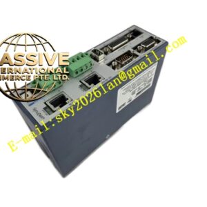
KONGSBERG RHUB200-5 Remote Hub Unit
Technical Specifications Model: RHUB200-5 Brand: Kongsberg Power Supply: 24V DC marine auxiliary power input Bus Interface: Multi-port marine fieldbus connection terminals Number of Branch Ports: 5 bus branch channels Operating Temperature: -10 ℃ ~ +55 ℃ Storage Temperature: -25 ℃ ~ +70 ℃ Relative Humidity: 10% ~ 95%, non-condensing Mounting Style: NS35 DIN rail mounting inside marine control cabinet Protection Class: IP20 Environmental Compliance: Fully complies with marine classification society environmental standards
Functional Features Concentrates main marine fieldbus line and splits communication signal into 5 independent branch circuits for remote I/O modules. Distributes regulated 24V DC auxiliary power to connected field remote I/O equipment. Built-in bus termination resistor circuit for matching fieldbus characteristic impedance. Surge suppression circuit protects bus ports against transient voltage surges from marine power network. Real-time hardware monitoring of input power voltage and bus communication state. Front panel LED indicators display power supply status, bus running state and port fault alarm. Isolation circuit reduces cross-interference between different bus branch loops. Fault diagnosis function reports bus short-circuit or open-circuit events to main marine automation controller.
Application Scenarios Ship engine room automation network, offshore platform remote I/O signal distribution, cargo tank monitoring system bus junction, ballast control system fieldbus branching, vessel safety alarm system signal hub, thruster control system field communication network.
Performance Parameters Maintains stable bus signal transmission on all 5 branches under continuous hull vibration. Built-in surge protection circuit suppresses voltage spikes induced by marine electromagnetic environment. Power distribution channels deliver stable 24V DC output to connected remote I/O modules. Impedance matching circuit eliminates bus signal reflection and communication distortion. Fault detection circuit identifies bus line abnormality and uploads alarm signal immediately. Internal non-volatile memory stores fault event records for maintenance review.
Material Composition Housing: Flame-retardant black plastic front panel and metal electromagnetic shielding frame. Main PCB: FR4 multi-layer printed circuit board coated with thick conformal coating for salt mist and moisture resistance. Core Electronic Components: Bus signal isolation chips, surge suppression components, power distribution management IC, impedance matching resistors, voltage monitoring chip, non-volatile memory chip. Terminal Parts: Vibration-proof copper alloy screw terminals for bus and power wiring. Indicator Components: High-brightness multi-color LED status indicators mounted on front panel. Fasteners: Stainless steel anti-corrosion screws and DIN rail spring locking clip.
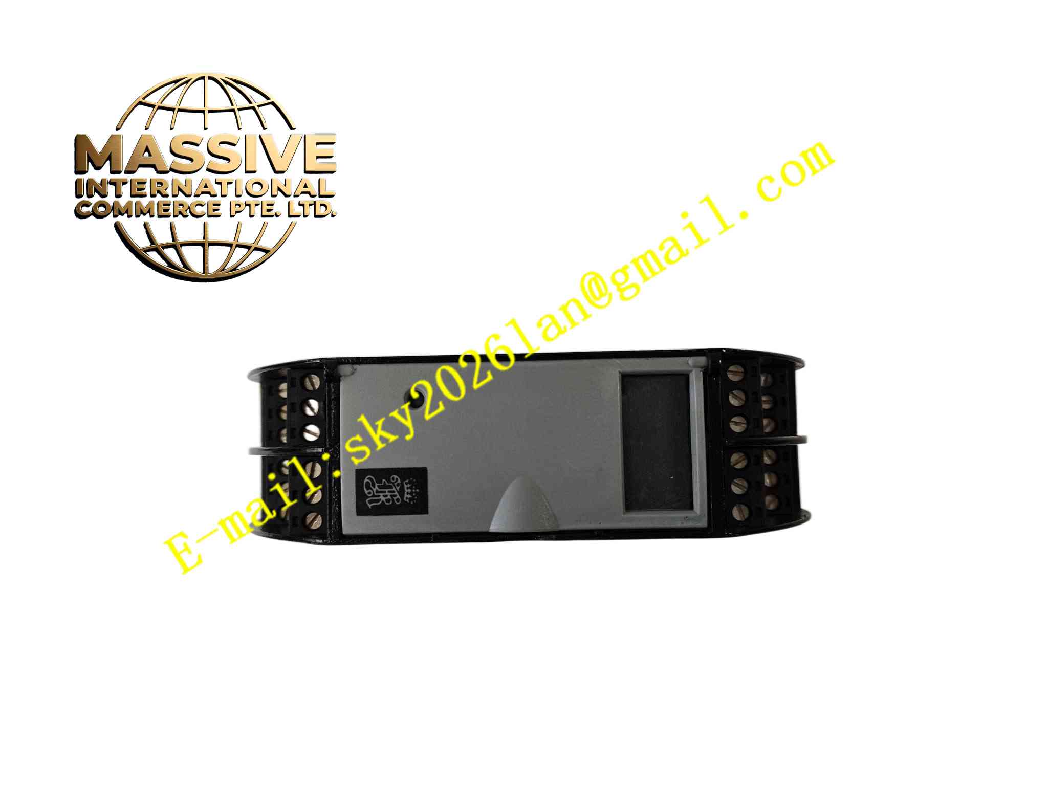
Structural Features Compact rectangular DIN rail module structure for installation inside marine electrical cabinets. Front panel integrates LED status indicators and permanent product identification marking. Rear side is equipped with screw terminals for main bus input, 5 branch bus ports and 24V DC power supply. Metal shielding frame wraps internal PCB to reduce external electromagnetic interference. Internal circuit layout separates high-current power distribution circuit and low-voltage bus signal circuit. PCB components use enhanced shock-resistant soldering technology to resist long-term marine vibration.
Working Principle 24V DC marine auxiliary power enters RHUB200-5 through power input terminals. Internal power management circuit stabilizes input voltage and distributes power to each branch port for connected remote I/O modules. The main marine fieldbus signal enters the hub through main bus terminals. Internal signal isolation and impedance matching circuit splits the main bus signal into 5 independent branch channels for downstream Kongsberg remote I/O units. The voltage monitoring chip continuously checks input power level, and bus monitoring circuit detects signal integrity and line fault. When bus short circuit, open circuit or power abnormality appears, fault LED activates and fault information transmits to the main marine automation controller through the bus network.
Installation Requirements Mount RHUB200-5 on NS35 standard DIN rail inside dry marine control cabinet and lock spring clip completely. Connect 24V DC marine power cable, main fieldbus cable and each branch bus cable to corresponding screw terminals strictly following wiring diagram. Use marine shielded twisted pair cables for all fieldbus wiring. Complete protective earth connection from module metal shielding frame to ship grounding system. Set bus terminal resistance configuration according to actual network topology. Carry out bus communication test and power output test after wiring completion. Reserve sufficient clearance around the module for natural air cooling.
Usage Precautions Inspect terminal screw tightness periodically, as continuous hull vibration loosens screw terminals. Maintain dry cabinet environment and avoid salt mist condensation inside cabinet. Do not apply voltage exceeding rated range to power and bus terminals. Do not disassemble module housing without professional authorization. Back up marine automation network configuration before hub replacement. Cut off module input power before modifying any bus wiring. Check cable insulation performance regularly in marine salt spray environment.