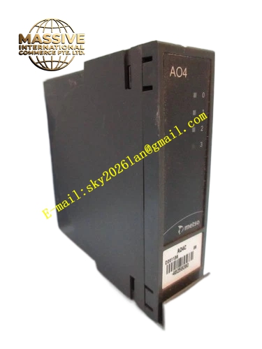
Description
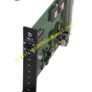
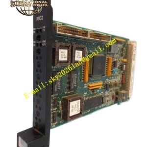
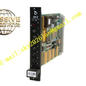
METSO D201136
Technical Specifications: 8‑channel RTD input; support PT100 and PT1000 thermal‑resistance sensors; compatible with 2‑wire, 3‑wire and 4‑wire connection modes; 16‑bit ADC conversion; per‑channel optoelectronic isolation; power supply 24 VDC from rack backplane; rack plug‑in installation; operating temperature range 0 ℃‑+55 ℃; each channel LED status indicator; protection class IP20.
Functional Features: Directly collect thermal‑resistance temperature signals; software configurable for different sensor wiring modes; hardware sensor wire‑break fault detection; independent electrical isolation for each channel; single‑channel fault isolation; module self‑diagnosis function; upload temperature measurement data and fault‑alarm information to DCS monitoring system.
Application Scenarios: Thermal power plant bearing and pipeline temperature‑monitoring cabinet; chemical plant reaction‑vessel temperature‑collection cabinet; pulp and paper mill cooking section temperature‑monitoring cabinet; water‑treatment plant equipment temperature‑monitoring cabinet.
Performance Parameters: Temperature‑measurement accuracy ±0.1 ℃; low long‑term temperature drift; high‑resolution analog‑to‑digital conversion; conform to industrial EMC electromagnetic‑compatibility standards; support 7×24 hours uninterrupted continuous operation.
Material Composition: Fiberglass epoxy multilayer PCB; high‑precision ADC chip; optoelectronic isolation components; gold‑plated edge connector; metal front panel; three‑proof conformal coating covered on circuit‑board surface.
Structural Features: Rack plug‑in modular card‑type structure; front panel equipped with LED indicators for power supply, running and channel‑fault status; rear gold‑plated edge connector connects with rack backplane bus; analog acquisition circuit and logic circuit realize physical separation; mechanical anti‑loose locking buckle fitted on front panel.
Working Principle: Field RTD sensor signals transmit to D201136 module through matched terminal base. Module outputs constant excitation current to thermal‑resistance element, collects resistance‑change value and converts resistance signal into digital temperature value via internal ADC chip. Temperature data transmits to DPU controller through backplane bus. Module detects sensor wire‑break or short‑circuit fault and uploads alarm‑message to upper monitoring system.
Installation Requirements: Install module into designated slot of Damatic XD I/O rack and cooperate with original matched terminal base. Adopt special shielded compensation cables for RTD sensor wiring. Cable shielding layer uses single‑point grounding. Temperature‑signal cables and high‑power cables are laid separately. Cabinet protective‑grounding terminal must realize reliable connection. Reserve adequate ventilation clearance for heat dissipation.
Precautions for Use: Select corresponding wiring mode according to actual field RTD sensor type. Cut off sensor‑loop power supply before wiring operation. Never feed high‑voltage signal into input channel. Cut off rack backplane power supply before removing module. Inspect wiring‑terminal tightness periodically. Prevent condensation inside control cabinet.