Description
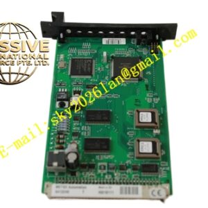
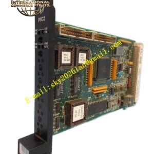
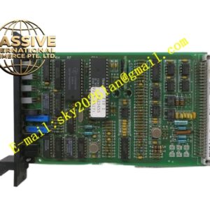
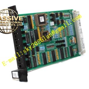
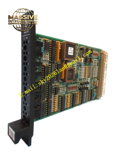
METSO S422737
Technical Specifications: Mixed digital input and output channels; input supports 24 VDC‑240 VAC signal; output contact rated current 10 A per channel; operating voltage range 24 VDC‑240 VAC; operating temperature range ‑20 ℃ to +60 ℃; support Modbus and Profibus communication protocol; protection class IP67.
Functional Features: Integrated discrete signal acquisition and switching output function; hardware over‑current and over‑voltage protection; loop fault diagnosis; channel‑level fault isolation; module self‑diagnosis function; upload status data and fault alarm information to upper control system.
Application Scenarios: Field‑mounted on‑site control cabinet for paper‑making workshop equipment; local control box for chemical plant on‑site valves; pump and valve on‑site control unit in water‑treatment project; mineral processing field equipment local control cabinet.
Performance Parameters: Fast signal response speed; strong surge‑resisting capacity for input‑output loops; stable contact performance under rated load; satisfy industrial EMC anti‑interference requirement; adapt to harsh on‑site working environment.
Material Composition: High‑strength flame‑retardant engineering plastic shell; industrial‑grade relay components; optoelectronic isolation chips; metal wiring terminals; internal PCB with three‑proof coating.
Structural Features: Compact box‑type field installation structure; external wiring terminals arranged on lower part of shell; LED status indicators exposed on front panel; internal input‑output circuit area separated physically; shell reaches IP67 protection grade for field harsh environment application.
Working Principle: Field switching feedback signals are transmitted to S422737 input terminals. Internal isolation circuit converts contact state into digital logic signal and transmits to controller. When receiving control command from upper system, internal relay component acts, output switching signal to drive field actuators. Module monitors each channel loop condition in real‑time and triggers alarm when abnormality appears.
Installation Requirements: Install module at designated on‑site position, fasten mounting screws. Use cables with suitable current‑carrying capacity for field wiring. Ensure cable sealing of shell wiring ports intact. Complete reliable protective grounding for module shell. Avoid direct sunlight and heavy rain soaking for installation position.
Precautions for Use: Strictly match input‑output signal voltage level before power‑on. Do not exceed rated current load of output channel. Cut off both system power and field load power before wiring maintenance. Inspect shell sealing performance periodically. Prevent corrosive gas erosion for module installation location.